This chapter discusses how data are represented and stored in a computer.
In the context of computing, boolean refers to a condition that can be either true or false and binary refers to the use of a base-2 numeric system to represent numbers.
RISC-V assembly language uses binary to represent all values, be they boolean or numeric. It is the context within which they are used that determines whether they are boolean or numeric.
Boolean functions apply on a per-bit basis. When applied to multi-bit values, each bit position is operated upon independent of the other bits.
RISC-V assembly language uses zero to represent false and one to represent true. In general, however, it is useful to relax this and define zero and only zero to be false and anything that is not false is therefore true.1
The reason for this relaxation is to describe the common case where the CPU processes data, multiple bits at-a-time.
These groups have names like byte (8 bits), halfword (16 bits) and fullword (32 bits).
The NOT operator applies to a single operand and represents the opposite of the input.
If the input is 1 then the output is 0. If the input is 0 then the output is 1. In other words, the output value is not that of the input value.
Expressing the not function in the form of a truth table:
| A | \(\overline {\mbox {A}}\) |
| 0 | 1 |
| 1 | 0 |
A truth table is drawn by indicating all of the possible input values on the left of the vertical bar with each row displaying the output values that correspond to the input for that row. The column headings are used to define the illustrated operation expressed using a mathematical notation. The not operation is indicated by the presence of an overline.
In computer programming languages, things like an overline can not be efficiently expressed using a standard keyboard. Therefore it is common to use a notation such as that used by the C language when discussing the NOT operator in symbolic form. Specifically the tilde: ‘~’.
It is also uncommon to for programming languages to express boolean operations on single-bit input(s). A more generalized operation is used that applies to a set of bits all at once. For example, performing a not operation of eight bits at once can be illustrated as:
  ~ 1 1 1 1 0 1 0 1  <== A
  -----------------
    0 0 0 0 1 0 1 0  <== output
In a line of code the above might read like this: output = ~A
The boolean and function has two or more inputs and the output is a single bit. The output is 1 if and only if all of the input values are 1. Otherwise it is 0.
This function works like it does in spoken language. For example if A is 1 and B is 1 then the output is 1 (true). Otherwise the output is 0 (false).
In mathematical notion, the and operator is expressed the same way as is multiplication. That is by a raised dot between, or by juxtaposition of, two variable names. It is also worth noting that, in base-2, the and operation actually is multiplication!
| A | B | AB |
| 0 | 0 | 0 |
| 0 | 1 | 0 |
| 1 | 0 | 0 |
| 1 | 1 | 1 |
This text will use the operator used in the C language when discussing the and operator in symbolic form. Specifically the ampersand: ‘&’.
An eight-bit example:
    1 1 1 1 0 1 0 1  <== A
  & 1 0 0 1 0 0 1 1  <== B
  -----------------
    1 0 0 1 0 0 0 1  <== output
In a line of code the above might read like this: output = A & B
The boolean or function has two or more inputs and the output is a single bit. The output is 1 if at least one of the input values are 1.
This function works like it does in spoken language. For example if A is 1 or B is 1 then the output is 1 (true). Otherwise the output is 0 (false).
In mathematical notion, the or operator is expressed using the plus (\(+\)).
| A | B | A\(+\)B |
| 0 | 0 | 0 |
| 0 | 1 | 1 |
| 1 | 0 | 1 |
| 1 | 1 | 1 |
This text will use the operator used in the C language when discussing the or operator in symbolic form. Specifically the pipe: ‘|’.
An eight-bit example:
    1 1 1 1 0 1 0 1  <== A
  | 1 0 0 1 0 0 1 1  <== B
  -----------------
    1 1 1 1 0 1 1 1  <== output
In a line of code the above might read like this: output = A | B
The boolean exclusive or function has two or more inputs and the output is a single bit. The output is 1 if only an odd number of inputs are 1. Otherwise the output will be 0.
Note that when xor is used with two inputs, the output is set to 1 (true) when the inputs have different values and 0 (false) when the inputs both have the same value.
In mathematical notion, the xor operator is expressed using the plus in a circle (\(\oplus \)).
| A | B | A\(\oplus {}\)B |
| 0 | 0 | 0 |
| 0 | 1 | 1 |
| 1 | 0 | 1 |
| 1 | 1 | 0 |
This text will use the operator used in the C language when discussing the xor operator in symbolic form. Specifically the carrot: ‘^’.
An eight-bit example:
    1 1 1 1 0 1 0 1  <== A
  ^ 1 0 0 1 0 0 1 1  <== B
  -----------------
    0 1 1 0 0 1 1 0  <== output
In a line of code the above might read like this: output = A ^ B
A binary integer is constructed with only 1s and 0s in the same manner as decimal numbers are constructed with values from 0 to 9.
Counting in binary (base-2) uses the same basic rules as decimal (base-10). The difference is when we consider that there are ten decimal digits and only two binary digits. Therefore, in base-10, we must carry when adding one to nine (because there is no digit representing a ten) and, in base-2, we must carry when adding one to one (because there is no digit representing a two.)
Figure 2.1 shows an abridged table of the decimal, binary and hexadecimal values ranging from \(0_{10}\) to \(128_{10}\).
| Decimal | Binary | Hex
| ||||||||||
| \(10^2\) | \(10^1\) | \(10^0\) | \(2^7\) | \(2^6\) | \(2^5\) | \(2^4\) | \(2^3\) | \(2^2\) | \(2^1\) | \(2^0\) | \(16^1\) | \(16^0\) |
| 100 | 10 | 1 | 128 | 64 | 32 | 16 | 8 | 4 | 2 | 1 | 16 | 1 |
| 0 | 0 | 0 | 0 | 0 | 0 | 0 | 0 | 0 | 0 | 0 | 0 | 0 |
| 0 | 0 | 1 | 0 | 0 | 0 | 0 | 0 | 0 | 0 | 1 | 0 | 1 |
| 0 | 0 | 2 | 0 | 0 | 0 | 0 | 0 | 0 | 1 | 0 | 0 | 2 |
| 0 | 0 | 3 | 0 | 0 | 0 | 0 | 0 | 0 | 1 | 1 | 0 | 3 |
| 0 | 0 | 4 | 0 | 0 | 0 | 0 | 0 | 1 | 0 | 0 | 0 | 4 |
| 0 | 0 | 5 | 0 | 0 | 0 | 0 | 0 | 1 | 0 | 1 | 0 | 5 |
| 0 | 0 | 6 | 0 | 0 | 0 | 0 | 0 | 1 | 1 | 0 | 0 | 6 |
| 0 | 0 | 7 | 0 | 0 | 0 | 0 | 0 | 1 | 1 | 1 | 0 | 7 |
| 0 | 0 | 8 | 0 | 0 | 0 | 0 | 1 | 0 | 0 | 0 | 0 | 8 |
| 0 | 0 | 9 | 0 | 0 | 0 | 0 | 1 | 0 | 0 | 1 | 0 | 9 |
| 0 | 1 | 0 | 0 | 0 | 0 | 0 | 1 | 0 | 1 | 0 | 0 | a |
| 0 | 1 | 1 | 0 | 0 | 0 | 0 | 1 | 0 | 1 | 1 | 0 | b |
| 0 | 1 | 2 | 0 | 0 | 0 | 0 | 1 | 1 | 0 | 0 | 0 | c |
| 0 | 1 | 3 | 0 | 0 | 0 | 0 | 1 | 1 | 0 | 1 | 0 | d |
| 0 | 1 | 4 | 0 | 0 | 0 | 0 | 1 | 1 | 1 | 0 | 0 | e |
| 0 | 1 | 5 | 0 | 0 | 0 | 0 | 1 | 1 | 1 | 1 | 0 | f |
| 0 | 1 | 6 | 0 | 0 | 0 | 1 | 0 | 0 | 0 | 0 | 1 | 0 |
| 0 | 1 | 7 | 0 | 0 | 0 | 1 | 0 | 0 | 0 | 1 | 1 | 1 |
| … | … | …
| ||||||||||
| 1 | 2 | 5 | 0 | 1 | 1 | 1 | 1 | 1 | 0 | 1 | 7 | d |
| 1 | 2 | 6 | 0 | 1 | 1 | 1 | 1 | 1 | 1 | 0 | 7 | e |
| 1 | 2 | 7 | 0 | 1 | 1 | 1 | 1 | 1 | 1 | 1 | 7 | f |
| 1 | 2 | 8 | 1 | 0 | 0 | 0 | 0 | 0 | 0 | 0 | 8 | 0 |
One way to look at this table is on a per-row basis where each place value is represented by the base raised to the power of the place value position (shown in the column headings.) For example to interpret the decimal value on the fourth row:
\begin {equation} 0 \times 10^2 + 0 \times 10^1 + 3 \times 10^0 = 3_{10} \end {equation}
Interpreting the binary value on the fourth row by converting it to decimal:
\begin {equation} 0 \times 2^7 + 0 \times 2^6 +0 \times 2^5 +0 \times 2^4 +0 \times 2^3 +0 \times 2^2 + 1 \times 2^1 + 1 \times 2^0 = 3_{10} \end {equation}
Interpreting the hexadecimal value on the fourth row by converting it to decimal:
\begin {equation} 0 \times 16^1 + 3 \times 16^0 = 3_{10} \end {equation}
We refer to the place values with the largest exponent (the one furthest to the left for any given base) as the most significant digit and the place value with the lowest exponent as the least significant digit. For binary numbers these are the Most Significant Bit (MSB) and Least Significant Bit (LSB) respectively.2
Another way to look at this table is on a per-column basis. When tasked with drawing such a table by hand, it might be useful to observe that, just as in decimal, the right-most column will cycle through all of the values represented in the chosen base then cycle back to zero and repeat. (For example, in binary this pattern is 0-1-0-1-0-1-0-…) The next column in each base will cycle in the same manner except each of the values is repeated as many times as is represented by the place value (in the case of decimal, \(10^1\) times, binary \(2^1\) times, hex \(16^1\) times. Again, the binary numbers for this pattern are 0-0-1-1-0-0-1-1-…) This continues for as many columns as are needed to represent the magnitude of the desired number.
Another item worth noting is that any even binary number will always have a 0 LSB and odd numbers will always have a 1 LSB.
As is customary in decimal, leading zeros are sometimes not shown for readability.
The relationship between binary and hex values is also worth taking note. Because \(2^4 = 16\), there is a clean and simple grouping of 4 bits to 1 hit (aka nybble). There is no such relationship between binary and decimal.
Writing and reading numbers in binary that are longer than 8 bits is cumbersome and prone to error. The simple conversion between binary and hex makes hex a convenient shorthand for expressing binary values in many situations.
For example, consider the following value expressed in binary, hexadecimal and decimal (spaced to show the relationship between binary and hex):
Binary value:       0010 0111 1011 1010 1100 1100 1111 0101
Hex Value:             2    7    B    A    C    C    F    5
Decimal Value:                                    666553589
Empirically we can see that grouping the bits into sets of four allows an easy conversion to hex and expressing it as such is \(\frac {1}{4}\) as long as in binary while at the same time allowing for easy conversion back to binary.
The decimal value in this example does not easily convey a sense of the binary value.
In programming languages like the C, its derivatives and RISC-V assembly, numeric values are interpreted as decimal unless they start with a zero (0). Numbers that start with 0 are interpreted as octal (base-8), numbers starting with 0x are interpreted as hexadecimal and numbers that start with 0b are interpreted as binary.
It is occasionally necessary to convert between decimal, binary and/or hex.
To convert from binary to decimal, put the decimal value of the place values …8, 4, 2, 1 over the binary digits like this:
Base-2 place values: 128 64 32 16  8  4  2  1
Binary:                0  0  0  1  1  0  1  1
Decimal:                       16 +8    +2 +1 = 27
Now sum the place-values that are expressed in decimal for each bit with the value of 1: \(16+8+2+1\). The integer binary value \(00011011_2\) represents the decimal value \(27_{10}\).
Conversion from binary to hex involves grouping the bits into sets of four and then performing the same summing process as shown above. If there is not a multiple of four bits then extend the binary to the left with zeros to make it so.
Grouping the bits into sets of four and summing:
Base-2 place values:   8 4 2 1     8 4 2 1     8 4 2 1     8 4 2 1
Binary:                0 1 1 0     1 1 0 1     1 0 1 0     1 1 1 0
Decimal:                 4+2  =6   8+4+  1=13  8+  2  =10  8+4+2  =14
After the summing, convert each decimal value to hex. The decimal values from 0–9 are the same values in hex. Because we don’t have any more numerals to represent the values from 10-15, we use the first 6 letters (See the right-most column of Figure 2.1.) Fortunately there are only six hex mappings involving letters. Thus it is reasonable to memorize them.
Continuing this example:
Decimal:               6           13          10          14
Hex:                   6           D           A           E
The four-bit mapping between binary and hex makes this task as straight forward as using a look-up table to translate each hit (Hex digIT) it to its unique four-bit pattern.
Perform this task either by memorizing each of the 16 patterns or by converting each hit to decimal first and then converting each four-bit binary value to decimal using the place-value summing method discussed in subsubsection 2.2.1.1.
For example:
Hex:                     7          C
Decimal Sum:       4+2+1=7  8+4    =12
Binary:          0 1 1 1    1 1 0 0
To convert arbitrary decimal numbers to binary, extend the list of binary place values until it exceeds the value of the decimal number being converted. Then make successive subtractions of each of the place values that would yield a non-negative result.
For example, to convert \(1234_{10}\) to binary:
Base-2 place values: 2048-1024-512-256-128-64-32-16-8-4-2-1

   0          2048      (too big)
   1   1234 - 1024 = 210
   0          512       (too big)
   0          256       (too big)
   1    210 - 128  = 82
   1     82 - 64   = 18
   0          32        (too big)
   1     18 - 16   = 2
   0          8         (too big)
   0          4         (too big)
   1      2 - 2    = 0
   0          1         (too big)
The answer using this notation is listed vertically in the left column with the MSB on the top and the LSB on the bottom line: \(010011010010_2\).
Conversion from decimal to hex can be done by using the place values for base-16 and the same math as from decimal to binary or by first converting the decimal value to binary and then from binary to hex by using the methods discussed above.
Because binary and hex are so closely related, performing a conversion by way of binary is straight forward.
The addition of binary numbers can be performed long-hand the same way decimal addition is taught in grade school. In fact binary addition is easier since it only involves adding 0 or 1.
The first thing to note that in any number base \(0+0=0\), \(0+1=1\), and \(1+0=1\). Since there is no “two” in binary (just like there is no “ten” decimal) adding \(1+1\) results in a zero with a carry as in: \(1+1=10_2\) and in: \(1+1+1=11_2\). Using these five sums, any two binary integers can be added.
This truth table shows what is called a Full Addr. A full addr is a function that can add three input bits (the two addends and a carry value from a “prior column”) and produce the sum and carry output values.3
| \(ci\) | \(a\) | \(b\) | \(co\) | \(sum\) |
| 0 | 0 | 0 | 0 | 0 |
| 0 | 0 | 1 | 0 | 1 |
| 0 | 1 | 0 | 0 | 1 |
| 0 | 1 | 1 | 1 | 0 |
| 1 | 0 | 0 | 0 | 1 |
| 1 | 0 | 1 | 1 | 0 |
| 1 | 1 | 0 | 1 | 0 |
| 1 | 1 | 1 | 1 | 1 |
Adding two unsigned binary numbers using 16 full adders:
        111111  1111  <== carries
     0110101111001111 <== addend
   + 0000011101100011 <== addend
   ------------------
     0111001100110010 <== sum
Note that the carry “into” the LSB is zero.
There are multiple methods used to represent signed binary integers. The method used by most modern computers is called two’s complement.
A two’s complement number is encoded in such a manner as to simplify the hardware used to add, subtract and compare integers.
A simple method of thinking about two’s complement numbers is to negate the place value of the MSB. For example, the number one is represented the same as discussed before:
Base-2 place values:  -128 64 32 16  8  4  2  1
Binary:                  0  0  0  0  0  0  0  1
The MSB of any negative number in this format will always be 1. For example the value \(-1_{10}\) is:
Base-2 place values:  -128 64 32 16  8  4  2  1
Binary:                  1  1  1  1  1  1  1  1
…because: \(-128+64+32+16+8+4+2+1=-1\).
This format has the virtue of allowing the same addition logic discussed above to be used to calculate the sums of signed numbers as unsigned numbers.
Calculating the signed addition: \(4+5 = 9\)
       1    <== carries
     000100 <== 4 = 0 + 0 + 0 + 4 + 0 + 0
    +000101 <== 5 = 0 + 0 + 0 + 4 + 0 + 1
    -------
     001001 <== 9 = 0 + 0 + 8 + 0 + 0 + 1
Calculating the signed addition: \(-4+ -5 = -9\)
    1 11     <== carries
      111100 <== -4 = -32 + 16 + 8 + 4 + 0 + 0
     +111011 <== -5 = -32 + 16 + 8 + 0 + 2 + 1
   ---------
    1 110111 <== -9 (with a truncation) = -32 + 16 + 4 + 2 + 1 = -9
Calculating the signed addition: \(-1+1=0\)
   -128 64 32 16  8  4  2  1 <== place value
   1  1  1  1  1  1  1  1    <== carries
      1  1  1  1  1  1  1  1 <== addend (-1)
    + 0  0  0  0  0  0  0  1 <== addend (1)
      ----------------------
   1  0  0  0  0  0  0  0  0 <== sum (0 with a truncation)
In order for this to work, the carry out of the sum of the MSBs must be discarded.
Changing the sign on two’s complement numbers can be described as inverting all of the bits (which is also known as the one’s complement) and then add one.
For example, negating the number four:
   -128 64 32 16  8  4  2  1
      0  0  0  0  0  1  0  0 <== 4

                     1  1    <== carries
      1  1  1  1  1  0  1  1 <== one’s complement of 4
    + 0  0  0  0  0  0  0  1 <== plus 1
      ----------------------
      1  1  1  1  1  1  0  0 <== -4
This can be verified by adding 5 to the result and observe that the sum is 1:
   -128 64 32 16  8  4  2  1
  1   1  1  1  1  1          <== carries
      1  1  1  1  1  1  0  0 <== -4
    + 0  0  0  0  0  1  0  1 <== 5
      ----------------------
  1   0  0  0  0  0  0  0  1 <== 1 (with a truncation)
Note that the changing of the sign using this method is symmetric in that it is identical when converting from negative to positive and when converting from positive to negative: flip the bits and add 1.
For example, changing the value -4 to 4 to illustrate the reverse of the conversion above:
   -128 64 32 16  8  4  2  1
      1  1  1  1  1  1  0  0 <== -4

                     1  1    <== carries
      0  0  0  0  0  0  1  1 <== one’s complement of -4
    + 0  0  0  0  0  0  0  1 <== plus 1
      ----------------------
      0  0  0  0  0  1  0  0 <== 4
Subtraction of binary numbers is performed by first negating the subtrahend and then adding the two numbers. Due to the nature of two’s complement numbers this method will work for both signed and unsigned numbers!
Observation: Since we always have a carry-in of zero into the LSB when adding, we can take advantage of that fact by (ab)using that carry input to perform that adding the extra 1 to the subtrahend as part of changing its sign in the examples below.
An example showing the subtraction of two signed binary numbers: \(-4-8 = -12\)
   -128 64 32 16  8  4  2  1
      1  1  1  1  1  1  0  0 <== -4  (minuend)
    - 0  0  0  0  1  0  0  0 <== 8   (subtrahend)
    ------------------------


  1   1  1  1  1  1  1  1  1 <== carries
      1  1  1  1  1  1  0  0 <== -4
    + 1  1  1  1  0  1  1  1 <== one’s complement of 8
    ------------------------
  1   1  1  1  1  0  1  0  0 <== -12
Discarding the carry bit that can be generated from the MSB is called truncation.
So far we have been ignoring the carries that can come from the MSBs when adding and subtracting. We have also been ignoring the potential impact of a carry causing a signed number to change its sign in an unexpected way.
In the examples above, truncating the results either had 1) no impact on the calculated sums or 2) was absolutely necessary to correct the sum in cases such as: \(-4 + 5\).
For example, note what happens when we try to subtract 1 from the most negative value that we can represent in a 4 bit two’s complement number:
     -8  4  2  1


      1  0  0  0 <== -8  (minuend)
    - 0  0  0  1 <==  1  (subtrahend)
    ------------


   1           1 <== carries
      1  0  0  0 <== -8
    + 1  1  1  0 <== one’s complement of 1
      ----------
   1  0  1  1  1 <== this SHOULD be -9 but with truncation it is 7
The problem with this example is that we can not represent \(-9_{10}\) using a 4-bit two’s complement number.
Granted, if we would have used 5 bit numbers, then the “answer” would have fit OK. But the same problem would return when trying to calculate \(-16 - 1\). So simply “making more room” does not solve this problem.
This is not just a problem when subtracting, nor is it just a problem with signed numbers.
The same situation can happen unsigned numbers. For example:
      8  4  2  1
  1   1  1  0  0 <== carries
      1  1  1  0 <== 14  (addend)
    + 0  0  1  1 <==  3  (addend)
    ------------
  1   0  0  0  1 <== this SHOULD be 17 but with truncation it is 1
How to handle such a truncation depends on whether the original values being added are signed or unsigned.
The RV ISA refers to the discarding the carry out of the MSB after an add (or subtract) of two unsigned numbers as an unsigned overflow4 and the situation where carries create an incorrect sign in the result of adding (or subtracting) two signed numbers as a signed overflow. [?, p. 13]
When adding unsigned numbers, an overflow only occurs when there is a carry out of the MSB resulting in a sum that is truncated to fit into the number of bits allocated to contain the result.
Figure 2.2 illustrates an unsigned overflow during addition:
Some times an overflow like this is referred to as a wrap around because of the way that successive additions will result in a value that increases until it wraps back around to zero and then returns to increasing in value until it, again, wraps around again.
When adding, unsigned overflow occurs when ever there is a carry out of the most significant bit.
When subtracting unsigned numbers, an overflow only occurs when the subtrahend is greater than the minuend (because in those cases the different would have to be negative and there are no negative values that can be represented with an unsigned binary number.)
Figure 2.3 illustrates an unsigned overflow during subtraction:
When subtracting, unsigned overflow occurs when ever there is not a carry out of the most significant bit (IFF the carry-in on the LSB is used to add the extra 1 to the subtrahend when changing its sign.)
When adding signed numbers, an overflow only occurs when the two addends are positive and sum is negative or the addends are both negative and the sum is positive.
When subtracting signed numbers, an overflow only occurs when the minuend is positive and the subtrahend is negative and difference is negative or when the minuend is negative and the subtrahend is positive and the difference is positive.5
Consider the results of the addition of two signed numbers while looking more closely at the carry values.
Figure 2.4 is an example of signed overflow. As shown, the problem is that the sum of two positive numbers has resulted in an obviously incorrect negative result due to a carry flowing into the sign-bit in the MSB.
Granted, if the same values were added using values larger than 8-bits then the sum would have been correct. However, these examples assume that all the operations are performed on (and results stored into) 8-bit values. Given any finite-number of bits, there are values that could be added such that an overflow occurs.
Figure 2.5 shows another overflow situation that is caused by the fact that there is nowhere for the carry out of the sign-bit to go. We say that this result has been truncated.
Truncation is not necessarily a problem. Consider the truncations in figures 2.6 and 2.7. Figure 2.7 demonstrates the importance of discarding the carry from the sum of the MSBs of signed numbers when addends do not have the same sign.
Just like an unsigned number can wrap around as a result of successive additions, a signed number can so the same thing. The only difference is that signed numbers won’t wrap from the maximum value back to zero, instead it will wrap from the most positive to the most negative value as shown in Figure 2.8.
Formally, a signed overflow occurs when ever the carry into the most significant bit is not the same as the carry out of the most significant bit.
Due to the nature of the two’s complement encoding scheme, the following numbers all represent the same value:
                                   1111 <== -1
                               11111111 <== -1
                   11111111111111111111 <== -1
           1111111111111111111111111111 <== -1
As do these:
                                  01100 <== 12
                             0000001100 <== 12
    00000000000000000000000000000001100 <== 12
The lengthening of these numbers by replicating the digits on the left is what is called sign extension.
Any signed number can have any quantity of additional MSBs added to it, provided that they repeat the value of the sign bit.
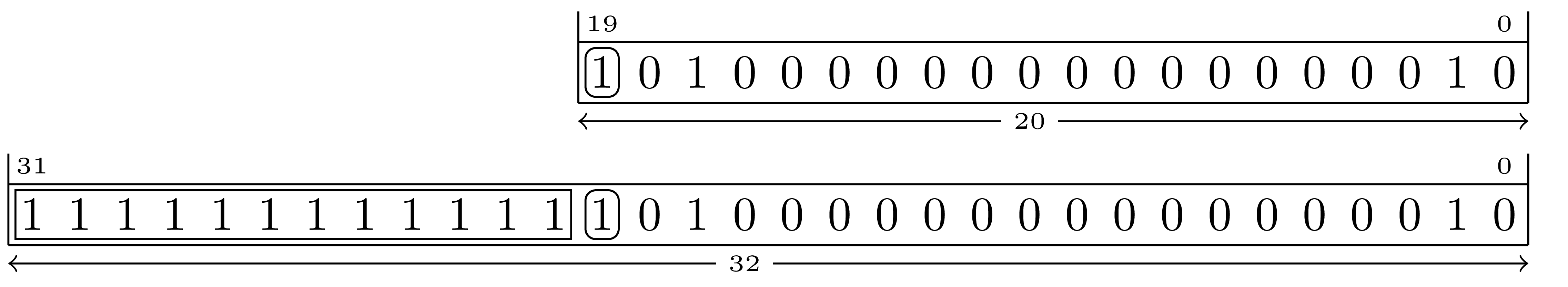
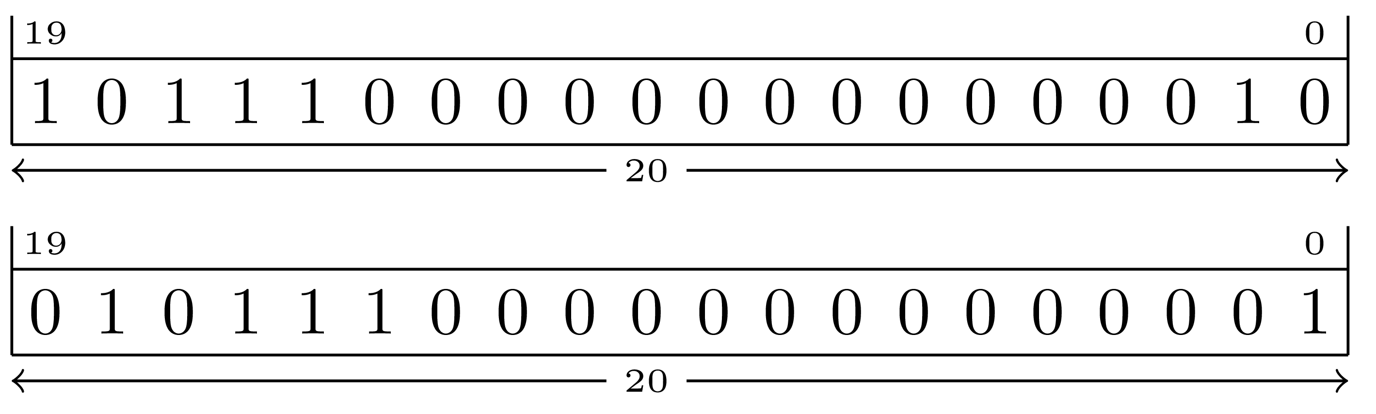
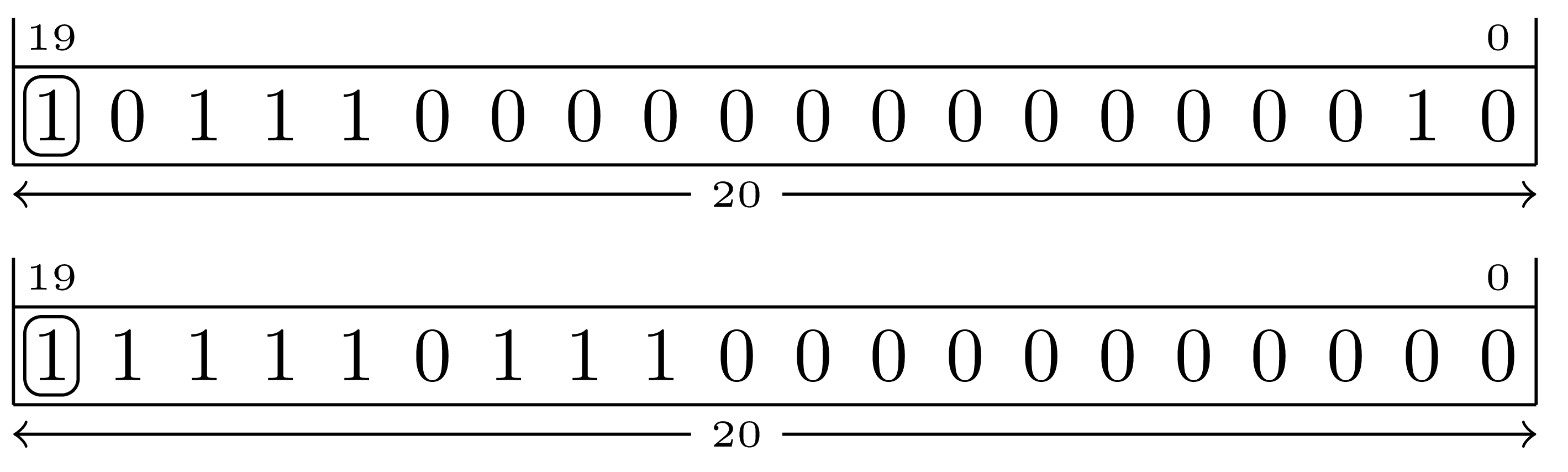
Figure 2.9 illustrates extending the negative sign bit to the left by replicating it. A negative number will have its MSB (bit 19 in this example) set to 1. Extending this value to the left will set all the new bits to the left of it to 1 as well.
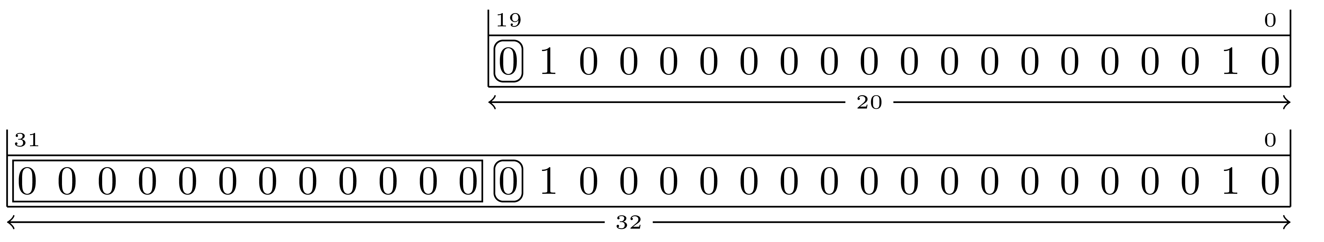
Figure 2.10 illustrates extending the sign bit of a positive number to the left by replicating it. A positive number will have its MSB set to 0. Extending this value to the left will set all the new bits to the left of it to 0 as well.
In a similar vein, any unsigned number also may have any quantity of additional MSBs added to it provided that they are all zero. This is called zero extension. For example, the following all represent the same value:
                                   1111 <== 15
                                  01111 <== 15
          00000000000000000000000001111 <== 15
Any unsigned number may be zero extended to any size.
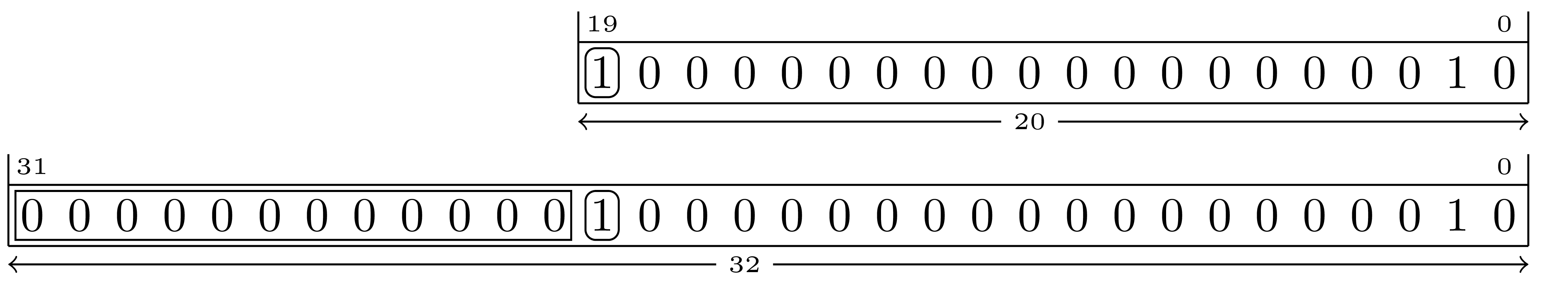
Figure 2.11 illustrates zero-extending a 20-bit number to the left to form a 32-bit number.
We were all taught how to multiply and divide decimal numbers by ten by moving (or shifting) the decimal point to the right or left respectively. Doing the same in any other base has the same effect in that it will multiply or divide the number by its base.
Multiplication and division are only two reasons for shifting. There can be other occasions where doing so is useful.
As implemented by a CPU, shifting applies to the value in a register and the results stored back into a register of finite size. Therefore a shift result will always be truncated to fit into a register.
Note that when dealing with numeric values, any truncation performed during a right-shift will manifest itself as rounding toward zero.
Shifting logically to the left or right is a matter of re-aligning the bits in a register and truncating the result.
To shift left two positions:
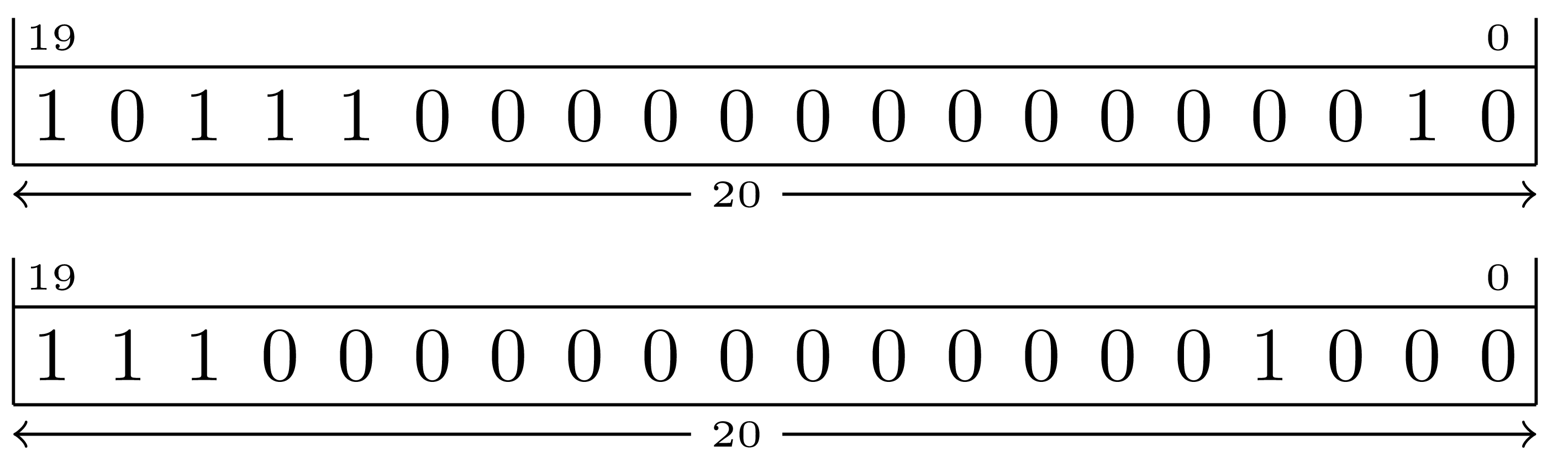
To shift right one position:
Note that the vacated bit positions are always filled with zero.
Some times it is desirable to retain the value of the sign bit when shifting. The RISC-V ISA provides an arithmetic right shift instruction for this purpose (there is no arithmetic left shift for this ISA.)
When shifting to the right arithmetically, vacated bit positions are filled by replicating the value of the sign bit.
An arithmetic right shift of a negative number by 4 bit positions:
As mentioned in subsubsection 1.1.1.1, the main memory in a RISC-V system is byte-addressable. For that reason we will visualize it by displaying ranges of bytes displayed in hex and in ASCII. As will become obvious, the ASCII part makes it easier to find text messages.6
subsection 2.1 shows a memory dump from the rvddt ‘d’ command requesting a dump starting at address 0x00002600 for the default quantity (0x100) of bytes.
 ddt> d 0x00002600
2 00002600: 93 05 00 00 13 06 00 00  93 06 00 00 13 07 00 00 *................*
3 00002610: 93 07 00 00 93 08 d0 05  73 00 00 00 63 54 05 02 *........s...cT..*
4 00002620: 13 01 01 ff 23 24 81 00  13 04 05 00 23 26 11 00 *....#$......#&..*
5 00002630: 33 04 80 40 97 00 00 00  e7 80 40 01 23 20 85 00 *3..@......@.# ..*
6 00002640: 6f 00 00 00 6f 00 00 00  b7 87 00 00 03 a5 07 43 *o...o..........C*
7 00002650: 67 80 00 00 00 00 00 00  76 61 6c 3d 00 00 00 00 *g.......val=....*
8 00002660: 00 00 00 00 80 84 2e 41  1f 85 45 41 80 40 9a 44 *.......A..EA.@.D*
9 00002670: 4f 11 f3 c3 6e 8a 67 41  20 1b 00 00 20 1b 00 00 *O...n.gA ... ...*
10 00002680: 44 1b 00 00 14 1b 00 00  14 1b 00 00 04 1c 00 00 *D...............*
11 00002690: 44 1b 00 00 14 1b 00 00  04 1c 00 00 14 1b 00 00 *D...............*
12 000026a0: 44 1b 00 00 10 1b 00 00  10 1b 00 00 10 1b 00 00 *D...............*
13 000026b0: 04 1c 00 00 54 1f 00 00  54 1f 00 00 d4 1f 00 00 *....T...T.......*
14 000026c0: 4c 1f 00 00 4c 1f 00 00  34 20 00 00 d4 1f 00 00 *L...L...4 ......*
15 000026d0: 4c 1f 00 00 34 20 00 00  4c 1f 00 00 d4 1f 00 00 *L...4 ..L.......*
16 000026e0: 48 1f 00 00 48 1f 00 00  48 1f 00 00 34 20 00 00 *H...H...H...4 ..*
17 000026f0: 00 01 02 02 03 03 03 03  04 04 04 04 04 04 04 04 *................*
The rvddt prompt showing the dump command.
From left to right. the dump is presented as the address of the first byte (0x00002600) followed by a colon, the value of the byte at address 0x00002600 expressed in hex, the next byte (at address 0x00002601) and so on for 16 bytes. There is a double-space between the 7th and 8th bytes to help provide a visual reference for the center to make it easy to locate bytes on the right end. For example, the byte at address 0x0000260c is four bytes to the right of byte number eight (at the gap) and contains 0x13. To the right of the 16-bytes is an asterisk-enclosed set of 16 columns showing the ASCII characters that each byte represents. If a byte has a value that corresponds to a printable character code, the character will be displayed. For any illegal/un-displayable byte values, a dot is shown to make it easier to count the columns.
More of the same as seen on \(\ell \) 2. The address at the left can be seen to advance by \(16_{10}\) (or \(10_{16}\)) for each line shown.
The choice of which end of a multi-byte value is to be stored at the lowest byte address is referred to as endianness. For example, if a CPU were to store a halfword into memory, should the byte containing the Most Significant Bit (MSB) (the big end) go first or does the byte with the Least Significant Bit (LSB) (the little end) go first?
On the one hand the choice is arbitrary. On the other hand, it is possible that the choice could impact the performance of the system.7
IBM mainframe CPUs and the 68000 family store their bytes in big-endian order. While the Intel Pentium and most embedded processors use little-endian order. Some CPUs are even bi-endian in that they have instructions that can change their order on the fly.
The RISC-V system uses the little-endian byte order.
Using the contents of ??, a big-endian CPU would interpret the contents as follows:
The 8-bit value read from address 0x00002658 would be 0x76.
The 8-bit value read from address 0x00002659 would be 0x61.
The 8-bit value read from address 0x0000265a would be 0x6c.
The 8-bit value read from address 0x0000265b would be 0x3d.
The 16-bit value read from address 0x00002658 would be 0x7661.
The 16-bit value read from address 0x0000265a would be 0x6c3d.
The 32-bit value read from address 0x00002658 would be 0x76616c3d.
Notice that in a big-endian system, the place values of the bits comprising the 0x76 (located at memory address 0x00002658) are different depending on the number of bytes representing the value that is being read.
For example, when a 16-bit value is read from 0x00002658 then the 76 represents the binary place values: \(2^{15}\) to \(2^8\). When a 32-bit value is read then the 76 represents the binary place values: \(2^{31}\) to \(2^{24}\). In other words the value read from the first memory location (with the lowest address), of the plurality of addresses containing the complete value being read, is always placed on the left end, into the Most Significant Bits. One might dare say that the 76 is placed at the end with the big place values.
More examples:
An 8-bit value read from address 0x00002624 would be 0x23.
An 8-bit value read from address 0x00002625 would be 0x24.
An 8-bit value read from address 0x00002626 would be 0x81.
An 8-bit value read from address 0x00002627 would be 0x00.
A 16-bit value read from address 0x00002624 would be 0x2324.
A 16-bit value read from address 0x00002626 would be 0x8100.
A 32-bit value read from address 0x00002624 would be 0x23248100.
Again, notice that the byte from memory address 0x00002624, regardless of the number of bytes comprising the complete value being fetched, will always appear on the left/big end of the final value.
On a big-endian system, the bytes in the dump are in the same order as they would be used by the CPU if it were to read them as a multi-byte value.
Using the contents of ??, a little-endian CPU would interpret the contents as follows:
An 8-bit value read from address 0x00002658 would be 0x76.
An 8-bit value read from address 0x00002659 would be 0x61.
An 8-bit value read from address 0x0000265a would be 0x6c.
An 8-bit value read from address 0x0000265b would be 0x3d.
A 16-bit value read from address 0x00002658 would be 0x6176.
A 16-bit value read from address 0x0000265a would be 0x3d6c.
A 32-bit value read from address 0x00002658 would be 0x3d6c6176.
Notice that in a little-endian system, the place values of the bits comprising the 0x76 (located at memory address 0x00002658) are the same regardless of the the number of bytes representing the value that is being read.
Unlike the behavior of a big-endian machine, when little-endian machine reads a 16-bit value from 0x00002658 the 76 represents the binary place values from \(2^{7}\) to \(2^0\). When a 32-bit value is read then the 76 (still) represents the binary place values from \(2^{7}\) to \(2^{0}\). In other words the value read from the first memory location (with the lowest address), of the plurality of addresses containing the complete value being read, is always placed on the right end, into the Least Significant Bits. One might say that the 76 is placed at the end with the little place values.
Also notice that it is the bytes are what are “reversed” in a little-endian system (not the hex digits.)
More examples:
The 8-bit value read from address 0x00002624 would be 0x23.
The 8-bit value read from address 0x00002625 would be 0x24.
The 8-bit value read from address 0x00002626 would be 0x81.
The 8-bit value read from address 0x00002627 would be 0x00.
The 16-bit value read from address 0x00002624 would be 0x2423.
The 16-bit value read from address 0x00002626 would be 0x0081.
The 32-bit value read from address 0x00002624 would be 0x00812423.
As above, notice that the byte from memory address 0x00002624, regardless of the number of bytes comprising the complete value being fetched, will always appear on the right/little end of the final value.
On a little-endian system, the bytes in the dump are in reverse order as they would be used by the CPU if it were to read them as a multi-byte value.
In the RISC-V ISA it is noted that
A minor point is that we have also found little-endian memory systems to be more natural for hardware designers. However, certain application areas, such as IP networking, operate on big-endian data structures, and so we leave open the possibility of non-standard big-endian or bi-endian systems.”[?, p. 6]
While Endianness defines how single values are stored in memory, the array defines how multiple values are stored.
An array is a data structure comprised of an ordered set of elements. This text will limit its definition of array to a plurality of elements that are all of the same type. Where type refers to the size (number of bytes) and representation (signed, unsigned,…) of each element.
In an array, the elements are stored adjacent to one another such that the address \(e\) of any element \(x[n]\) is:
\begin {equation} e = a + n * s \end {equation}
Where \(x\) is the name of the array, \(n\) is the element number of interest, \(e\) is the address of interest, \(a\) is the address of the first element in the array and \(s\) is the size (in bytes) of each element.
Given an array \(x\) containing \(m\) elements, \(x[0]\) is the first element of the array and \(x[m-1]\) is the last element of the array.8
Using this definition, and the memory dump shown in ??, and the knowledge that we are using a little-endian machine and given that \(a = \) 0x00002656 and \(s = 2\), the values of the first 8 elements of array \(x\) are:
\(x[0]\) is 0x0000 and is stored at 0x00002656.
\(x[1]\) is 0x6176 and is stored at 0x00002658.
\(x[2]\) is 0x3d6c and is stored at 0x0000265a.
\(x[3]\) is 0x0000 and is stored at 0x0000265c.
\(x[4]\) is 0x0000 and is stored at 0x00002660.
\(x[5]\) is 0x0000 and is stored at 0x00002662.
\(x[6]\) is 0x8480 and is stored at 0x00002664.
\(x[7]\) is 0x412e and is stored at 0x00002666.
In general, there is no fixed rule nor notion as to how many elements an array has. It is up to the programmer to ensure that the starting address and the number of elements in any given array (its size) are used properly so that data bytes outside an array are not accidentally used as elements.
There is, however, a common convention used for an array of characters that is used to hold a text message (called a character string or just string).
When an array is used to hold a string the element past the last character in the string is set to zero. This is because 1) zero is not a valid printable ASCII character and 2) it simplifies software in that knowing no more than the starting address of a string is all that is needed to processes it. Without this zero sentinel value (called a null terminator), some knowledge of the number of characters in the string would have to otherwise be conveyed to any code needing to consume or process the string.
In ??, the 5-byte long array starting at address 0x00002658 contains a string whose value can be expressed as either:
76 61 6c 3d 00
or
When the double-quoted text form is used, the GNU assembler used in this text differentiates between ascii and asciiz strings such that an ascii string is not null terminated and an asciiz string is null terminated.
The value of providing a method to create a string that is not null terminated is that a program may define a large string by concatenating a number of ascii strings together and following the last with a byte of zero to null-terminate it.
It is a common mistake to create a string with a missing null terminator. The result of printing such a string is that the string will be printed as well as whatever random data bytes in memory follow it until a byte whose value is zero is encountered by chance.
Data values can be interpreted differently depending on the context in which they are used. Assuming what a set of bytes is used for based on their contents can be very misleading! For example, there is a 0x76 at address 0x00002658. This is a ‘v’ is you use it as an ASCII (see chapter B.1.2) character, a \(118_{10}\) if it is an integer value and TRUE if it is a conditional.
With respect to memory and storage, alignment refers to the location of a data element when the address that it is stored is a precise multiple of a power-of-2.
The primary alignments of concern are typically 2 (a halfword), 4 (a fullword), 8 (a double word) and 16 (a quad-word) bytes.
For example, any data element that is aligned to 2-byte boundary must have an (hex) address that ends in any of: 0, 2, 4, 6, 8, A, C or E. Any 4-byte aligned element must be located at an address ending in 0, 4, 8 or C. An 8-byte aligned element at an address ending with 0 or 8, and 16-byte aligned elements must be located at addresses ending in zero.
Such alignments are important when exchanging data between the CPU and memory because the hardware implementations are optimized to transfer aligned data. Therefore, aligning data used by any program will reap the benefit of running faster.9
An element of data is considered to be aligned to its natural size when its address is an exact multiple of the number of bytes used to represent the data. Note that the ISA we are concerned with only operates on elements that have sizes that are powers of two.
For example, a 32-bit integer consumes one full word. If the four bytes are stored in main memory at an address than is a multiple of 4 then the integer is considered to naturally aligned.
The same would apply to 16-bit, 64-bit, 128-bit and other such values as they fit into 2, 8 and 16 byte elements respectively.
Some CPUs can deliver four (or more) bytes at the same time while others might only be capable of delivering one or two bytes at a time. Such differences in hardware typically impact the cost and performance of a system.10
The RISC-V ISA requires that all instructions be aligned to their natural boundaries.
Every possible instruction that an RV32I CPU can execute contains exactly 32 bits. Therefore they are always stored on a full word boundary. Any unaligned instruction is illegal.11
An attempt to fetch an instruction from an unaligned address will result in an error referred to as an alignment exception. This and other exceptions cause the CPU to stop executing the current instruction and start executing a different set of instructions that are prepared to handle the problem. Often an exception is handled by completely stopping the program in a way that is commonly referred to as a system or application crash.
1This is how true and false behave in C, C++, and many other languages as well as the common assembly language idioms discussed in this text.
2Changing the value of the MSB will have a more significant impact on the numeric value than changing the value of the LSB.
3Note that the sum could be expressed in Boolean Algebra as: \(sum = ci \oplus {} a \oplus {} b\)
4Most microprocessors refer to unsigned overflow simply as a carry condition.
5I had to look it up to remember which were which too… it is: minuend - subtrahend = difference.[?]
6Most of the memory dumps in this text are generated by rvddt and are shown on a per-byte basis without any attempt to reorder their values. Some other applications used to dump memory do not dump the bytes in address-order! It is important to know how your software tools operate when using them to dump the contents of memory and/or files.
7See[?] for some history of the big/little-endian “controversy.”
8Some computing languages (C, C++, Java, C#, Python, Perl,…) define an array such that the first element is indexed as \(x[0]\). While others (FORTRAN, MATLAB) define the first element of an array to be \(x[1]\).
9Alignment of data, while important for efficient performance, is not mandatory for RISC-V systems.[?, p. 19]
10The design and implementation choices that determine how any given system operates are part of what is called a system’s organization and is beyond the scope of this text. See [?] for more information on computer organization.
11This rule is relaxed by the C extension to allow an instruction to start at any even address.[?, p. 5]