When discussing instructions, the following abbreviations/notations are used:
XLEN represents the bit-length of an x register in the machine architecture. Possible values are 32,
64 and 128.
Sign extend val to the left.
This is used to convert a signed integer value expressed using some number of bits to a larger number of bits by adding more bits to the left. In doing so, the sign will be preserved. In this case val represents the least MSBs of the value.
For more on sign-extension see section 2.3.
Zero extend val to the left.
This is used to convert an unsigned integer value expressed using some number of bits to a larger number of bits by adding more bits to the left. In doing so, the new bits added will all be set to zero. As is the case with sx(val), val represents the LSBs of the final value.
For more on zero-extension see 2.3.
Zero extend val to the right.
Some times a binary value is encoded such that a set of bits represented by val are used to represent the MSBs of some longer (more bits) value. In this case it is necessary to append zeros to the right to convert val to the longer value.
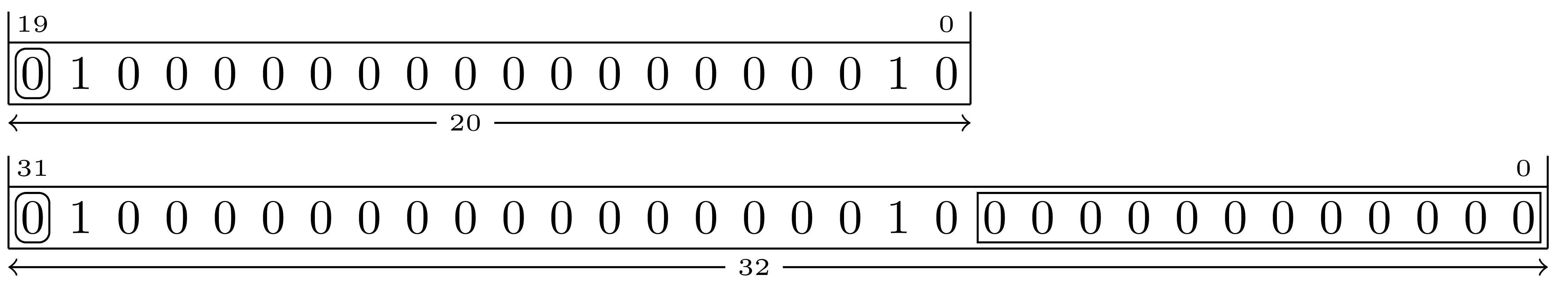
Figure 5.1 illustrates converting a 20-bit val to a 32-bit fullword.
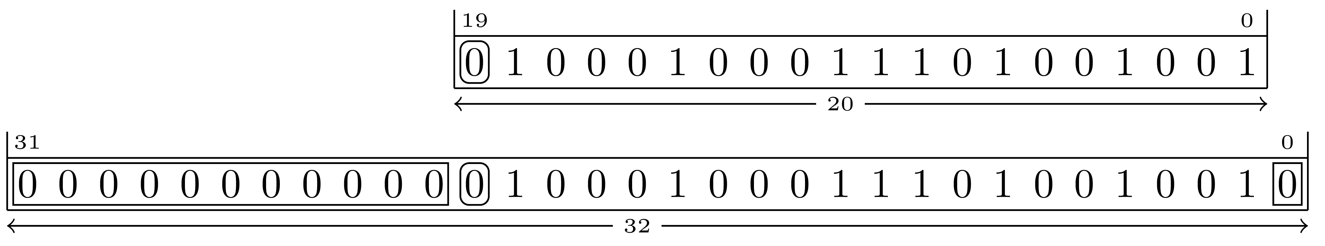
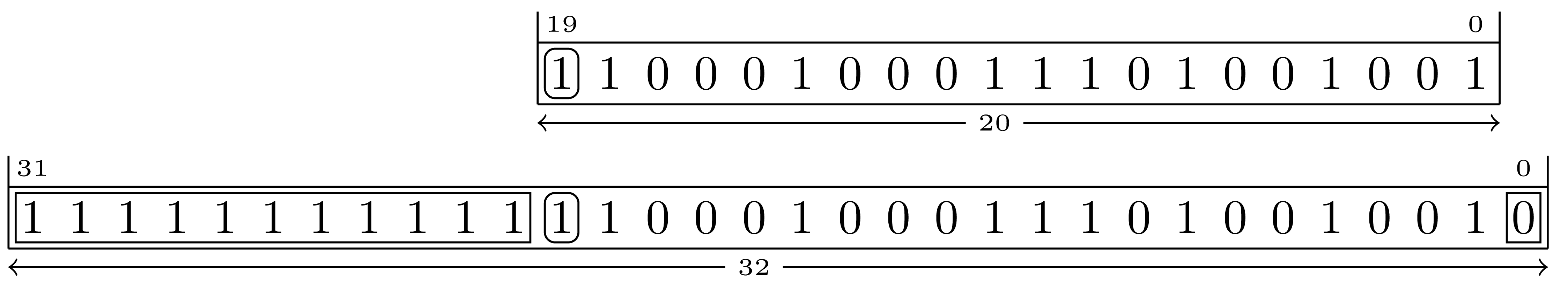
Some instructions such as the J-type (see subsection 5.3.2) include immediate operands that are extended in both directions.
Figure 5.2 and Figure 5.3 illustrates zero-extending a 20-bit negative number one bit to the right and sign-extending it 11 bits to the left:
The contents of an 8-bit value in memory at address addr.
Given the contents of the memory dump shown in Figure 5.4, m8(0x42) refers to the memory location at address 42\(_{16}\) that currently contains the 8-bit value fc\(_{16}\).
The m\(_n\)(addr) notation can be used to refer to memory that is being read or written depending on the context.
When memory is being written, the following notation is used to indicate that the least significant 8 bis of source will be is written into memory at the address addr:
m8(addr) \(\leftarrow \) source
When memory is being read, the following notation is used to indicate that the 8 bit value at the address addr will be read and stored into dest:
dest \(\leftarrow \) m8(addr)
Note that source and dest are typically registers.
The contents of an 16-bit little-endian value in memory at address addr.
Given the contents of the memory dump shown in Figure 5.4, m16(0x42) refers to the memory location at address 42\(_{16}\) that currently contains 65fc\(_{16}\). See also subsection 5.1.6.
The contents of an 32-bit little-endian value in memory at address addr.
Given the contents of the memory dump shown in Figure 5.4, m32(0x42) refers to the memory location at address 42\(_{16}\) that currently contains 662065fc\(_{16}\). See also subsection 5.1.6.
The contents of an 64-bit little-endian value in memory at address addr.
Given the contents of the memory dump shown in Figure 5.4, m64(0x42) refers to the memory location at address 42\(_{16}\) that currently contains 656c6c69662065fc\(_{16}\). See also subsection 5.1.6.
The contents of an 128-bit little-endian value in memory at address addr.
Given the contents of the memory dump shown in Figure 5.4, m128(0x42) refers to the memory location at address 42\(_{16}\) that currently contains 7220687469772064656c6c69662065fc\(_{16}\). See also subsection 5.1.6.
The address of the current instruction plus a numeric offset.
The address of the current instruction minus a numeric offset.
An address that is within \([-4096..4094]\) \([\)-0x1000..0x0ffe\(]\) of the current instruction location. These addresses are typically expressed in assembly source code by using labels. See subsection 5.3.6 for examples.
An address that is within \([-1048576..1048574]\) \([\)-0x100000..0x0ffffe\(]\) of the current instruction location. These addresses are typically expressed in assembly source code by using labels. See subsection 5.3.2 for an example.
The current value of the program counter.
An x-register used to store the result of instruction.
An x-register value used as a source operand for an instruction.
An x-register value used as a source operand for an instruction.
An immediate numeric operand. The word immediate refers to the fact that the operand is stored within an instruction.
The value of bits from h through l of x-register rsN. For example: rs1[15:0] refers to the contents of the 16 LSBs of rs1.
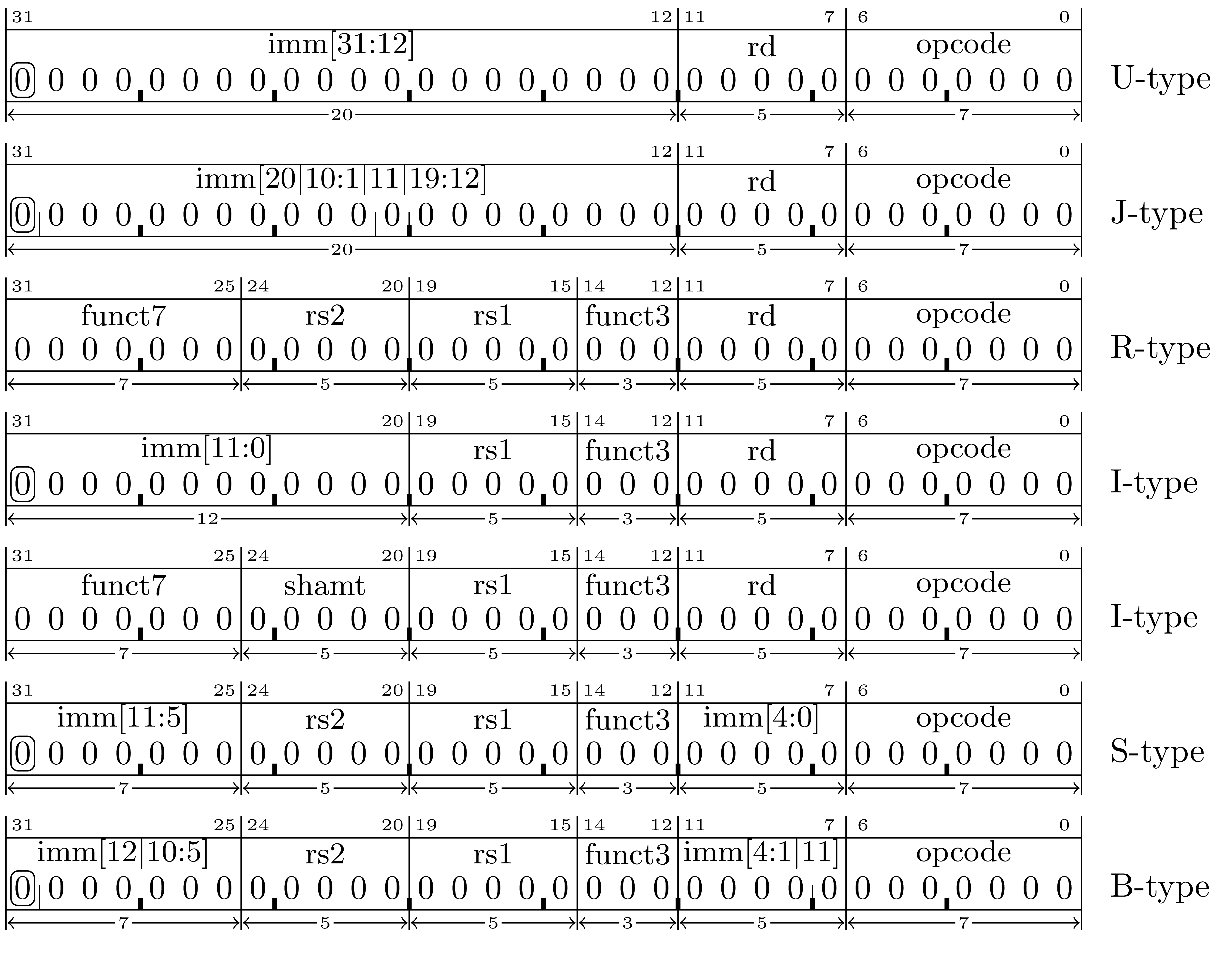
immediate, register, base-displacement, pc-relative
This document concerns itself with the RISC-V instruction formats shown in Figure 5.5.
The method/format of the instructions has been designed with an eye on the ease of future manufacture of the machine that will execute them. It is easier to build a machine if it does not have to accommodate many different ways to perform the same task. The result is that a machine can be built with fewer gates, consumes less power, and can run faster than if it were built when a priority is on how a user might prefer to decode the same instructions from a hex dump.
Observe that all instructions have their opcode in bits 0-6 and when they include an rd register it will be specified in bits 7-11, an rs1 register in bits 15-19, an rs2 register in bits 20-24, and so on. This has a seemingly strange impact on the placement of any immediate operands.
When immediate operands are present in an instruction, they are placed in the remaining unused bits. However, they are organized such that the sign bit is always in bit 31 and the remaining bits placed so as to minimize the number of places any given bit is located in different instructions.
For example, consider immediate operand bits 12-19. In the U-type format they are in bit positions 12-19. In the J-type format they are also in positions 12-19. In the J-type format immediate operand bits 1-10 are in the same instruction bit positions as they are in the I-type format and immediate operand bits 5-10 are in the same positions as they are in the B-type and S-type formats.
While this is inconvenient for anyone looking at a memory hexdump, it does make sense when considering the impact of this choice on the number of gates needed to implement circuitry to extract the immediate operands.
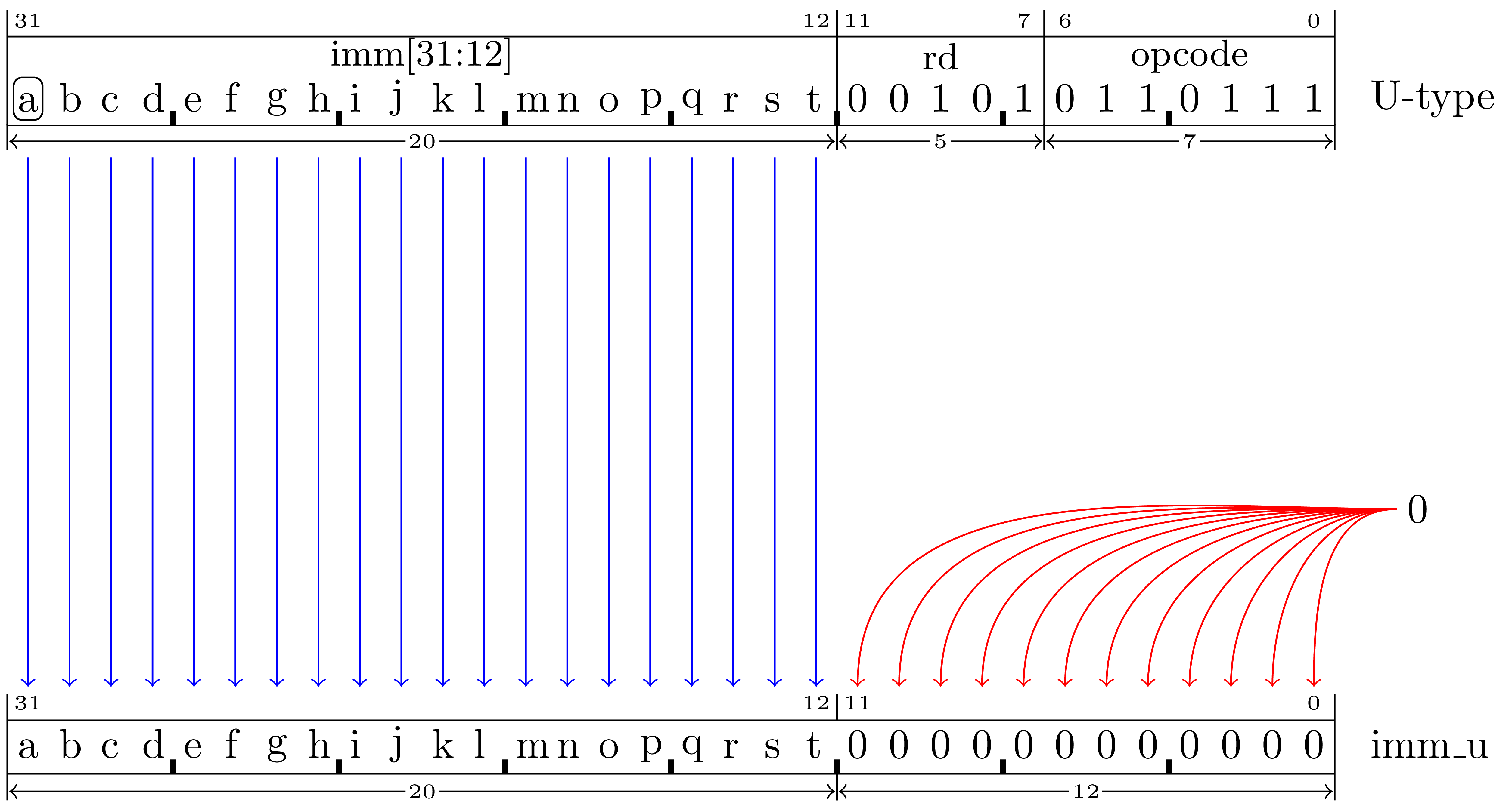
The U-Type format is used for instructions that use a 20-bit immediate operand and an rd destination register.
The rd field contains an x register number to be set to a value that depends on the instruction.
If XLEN=32 then the imm value will extracted from the instruction and converted as shown in Figure 5.6 to form the imm_u value.
Notice that the 20-bits of the imm field are mapped in the same order and in the same relative position that they appear in the instruction when they are used to create the value of the immediate operand. Leaving the imm bits on the left, in the “upper bits” of the imm_u value suggests a rationale for the name of this format.
lui rd,imm
Set register rd to the imm_u value as shown in Figure 5.6.
For example: lui x23,0x12345 will result in setting register x23 to the value 0x12345000.
auipc rd,imm
Add the address of the instruction to the imm_u value as shown Figure 5.6 and store the result in register rd.
For example, if the instruction auipc x22,0x10001 is executed from memory address 0x800012f4 then register x22 will be set to 0x900022f4.
If XLEN=64 then the imm_u value in this example will be converted to the same two’s complement integer value by extending the sign-bit further to the left.
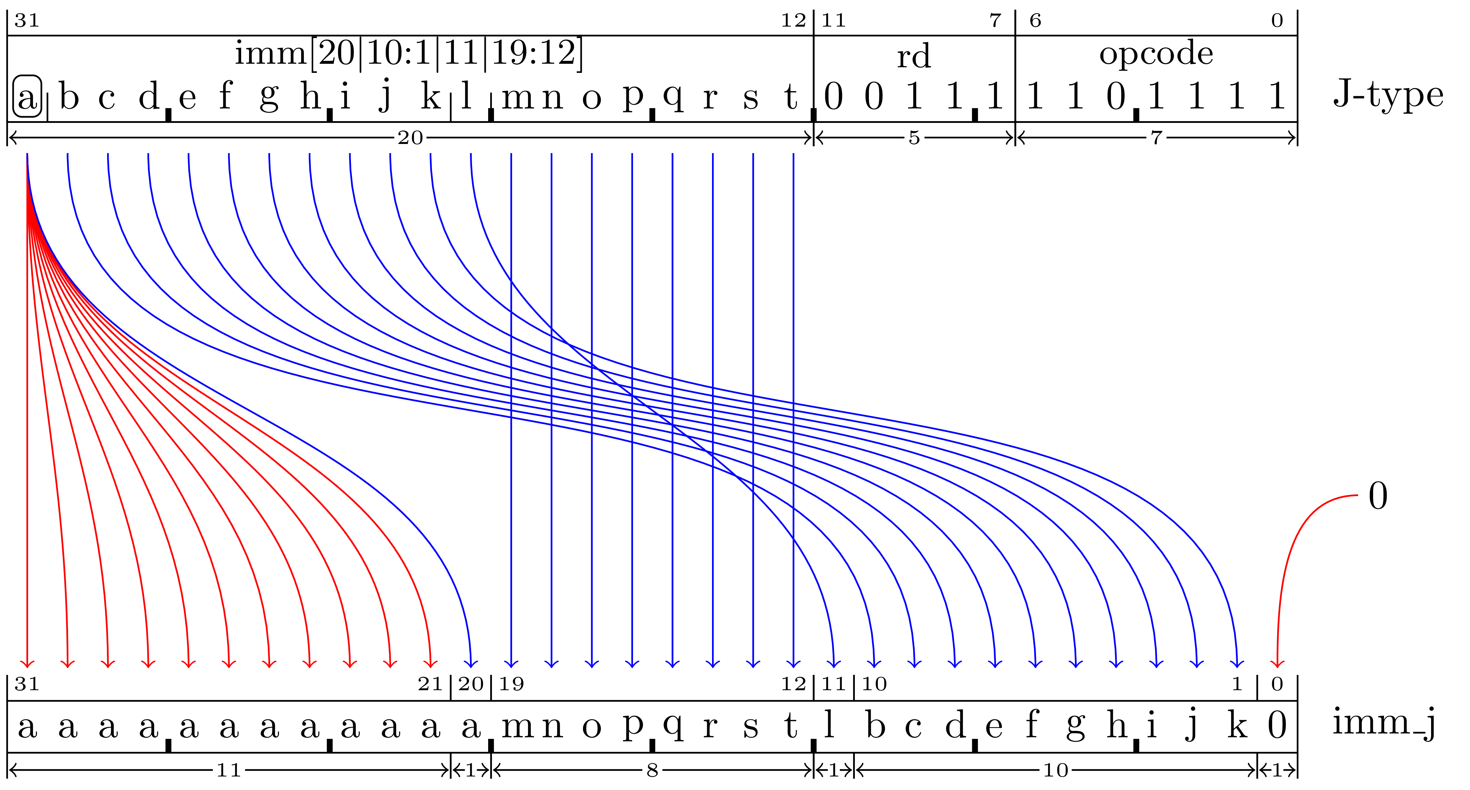
The J-type instruction format is used to encode the jal instruction with an immediate value that determines the jump target address. It is similar to the U-type, but the bits in the immediate operand are arranged in a different order.
Note that the imm_j value is an even 21-bit value in the range of \([-1048576..1048574]\) \([\)-0x100000..0x0ffffe\(]\) representing a pc-relative offset to the target address.
If XLEN=32 then the imm value will extracted from the instruction and converted as shown in Figure 5.7 to form the imm_j value.
The J-type format is used by the Jump And Link instruction that calculates the target address by adding imm_j to the current program counter. Since no instruction can be placed at an odd address the 20-bit imm value is zero-extended to the right to represent a 21-bit signed offset capable of expressing a wider range of target addresses than the 20-bit imm value alone.
jal rd,pcrel_21
Set register rd to the address of the next instruction that would otherwise be executed (the address of the jal instruction + 4) and then jump to the address given by the sum of the pc register and the imm_j value as decoded from the instruction shown in Figure 5.7.
Note that pcrel_21 is expressed in the instruction as a target address or label that is converted to a 21-bit value representing a pc-relative offset to the target address. For example, consider the jal instructions in the following code:
     00000010: 000002ef  jal    x5,0x10      # jump to self (address 0x10)
     00000014: 008002ef  jal    x5,0x1c      # jump to address 0x1c
     00000018: 00100073  ebreak
     0000001c: 00100073  ebreak
The instruction at address 0x10 has a target address of 0x10 and the imm_j is zero because offset from the “current instruction” to the target is zero.
The instruction at address 0x14 has a target address of 0x1c and the imm_j is 0x08 because 0x1c - 0x14 = 0x08.
See also subsection 5.3.6.
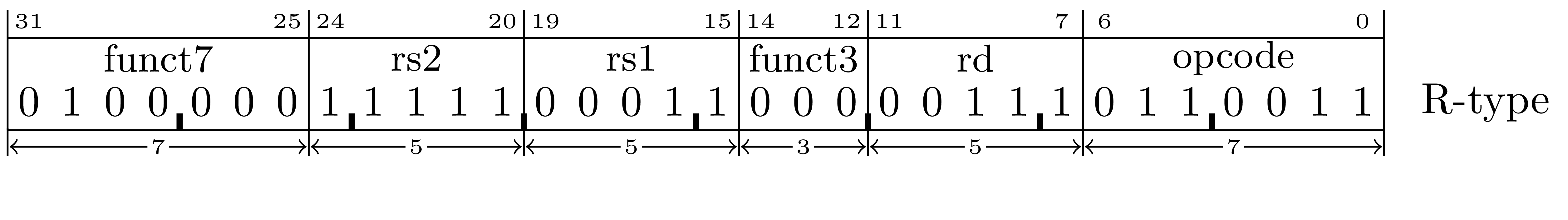
The R-type instructions are used for operations that set a destination register rd to the result of an arithmetic, logical or shift operation applied to source registers rs1 and rs2.
Note that instruction bit 30 (part of the the funct7 field) is used to select between the add and sub instructions as well as to select between srl and sra.
add rd,rs1,rs2
Set register rd to rs1 + rs2.
Note that the value of funct7 must be zero for this instruction. (The value of funct7 is how the add instruction is differentiated from the sub instruction.)
and rd,rs1,rs2
Set register rd to the bitwise and of rs1 and rs2.
For example, if x17 = 0x55551111 and x18 = 0xff00ff00 then the instruction and x12,x17,x18 will set x12 to the value 0x55001100.
or rd,rs1,rs2
Set register rd to the bitwise or of rs1 and rs2.
For example, if x17 = 0x55551111 and x18 = 0xff00ff00 then the instruction or x12,x17,x18 will set x12 to the value 0xff55ff11.
sll rd,rs1,rs2
Shift rs1 left by the number of bits specified in the least significant 5 bits of rs2 and store the result in rd.1
For example, if x17 = 0x12345678 and x18 = 0x08 then the instruction sll x12,x17,x18 will set x12 to the value 0x34567800.
slt rd,rs1,rs2
If the signed integer value in rs1 is less than the signed integer value in rs2 then set rd to 1. Otherwise, set rd to 0.
For example, if x17 = 0x12345678 and x18 = 0x0000ffff then the instruction slt x12,x17,x18 will set x12 to the value 0x00000000.
If x17 = 0x82345678 and x18 = 0x0000ffff then the instruction slt x12,x17,x18 will set x12 to the value 0x00000001.
sltu rd,rs1,rs2
If the unsigned integer value in rs1 is less than the unsigned integer value in rs2 then set rd to 1. Otherwise, set rd to 0.
For example, if x17 = 0x12345678 and x18 = 0x0000ffff then the instruction sltu x12,x17,x18 will set x12 to the value 0x00000000.
If x17 = 0x12345678 and x18 = 0x8000ffff then the instruction sltu x12,x17,x18 will set x12 to the value 0x00000001.
sra rd,rs1,rs2
Arithmetic-shift rs1 right by the number of bits given in the least-significant 5 bits of the rs2 register and store the result in rd.1
For example, if x17 = 0x87654321 and x18 = 0x08 then the instruction sra x12,x17,x18 will set x12 to the value 0xff876543.
If x17 = 0x76543210 and x18 = 0x08 then the instruction sra x12,x17,x18 will set x12 to the value 0x00765432.
Note that the value of funct7 must be zero for this instruction. (The value of funct7 is how the sra instruction is differentiated from the srl instruction.)
srl rd,rs1,rs2
Logic-shift rs1 right by the number of bits given in the least-significant 5 bits of the rs2 register and store the result in rd.1
For example, if x17 = 0x87654321 and x18 = 0x08 then the instruction srl x12,x17,x18 will set x12 to the value 0x00876543.
If x17 = 0x76543210 and x18 = 0x08 then the instruction srl x12,x17,x18 will set x12 to the value 0x00765432.
Note that the value of funct7 must be 0b0100000 for this instruction. (The value of funct7 is how the srl instruction is differentiated from the sra instruction.)
sub rd,rs1,rs2
Set register rd to rs1 - rs2.
Note that the value of funct7 must be 0b0100000 for this instruction. (The value of funct7 is how the sub instruction is differentiated from the add instruction.)
xor rd,rs1,rs2
Set register rd to the bitwise xor of rs1 and rs2.
For example, if x17 = 0x55551111 and x18 = 0xff00ff00 then the instruction xor x12,x17,x18 will set x12 to the value 0xaa55ee11.
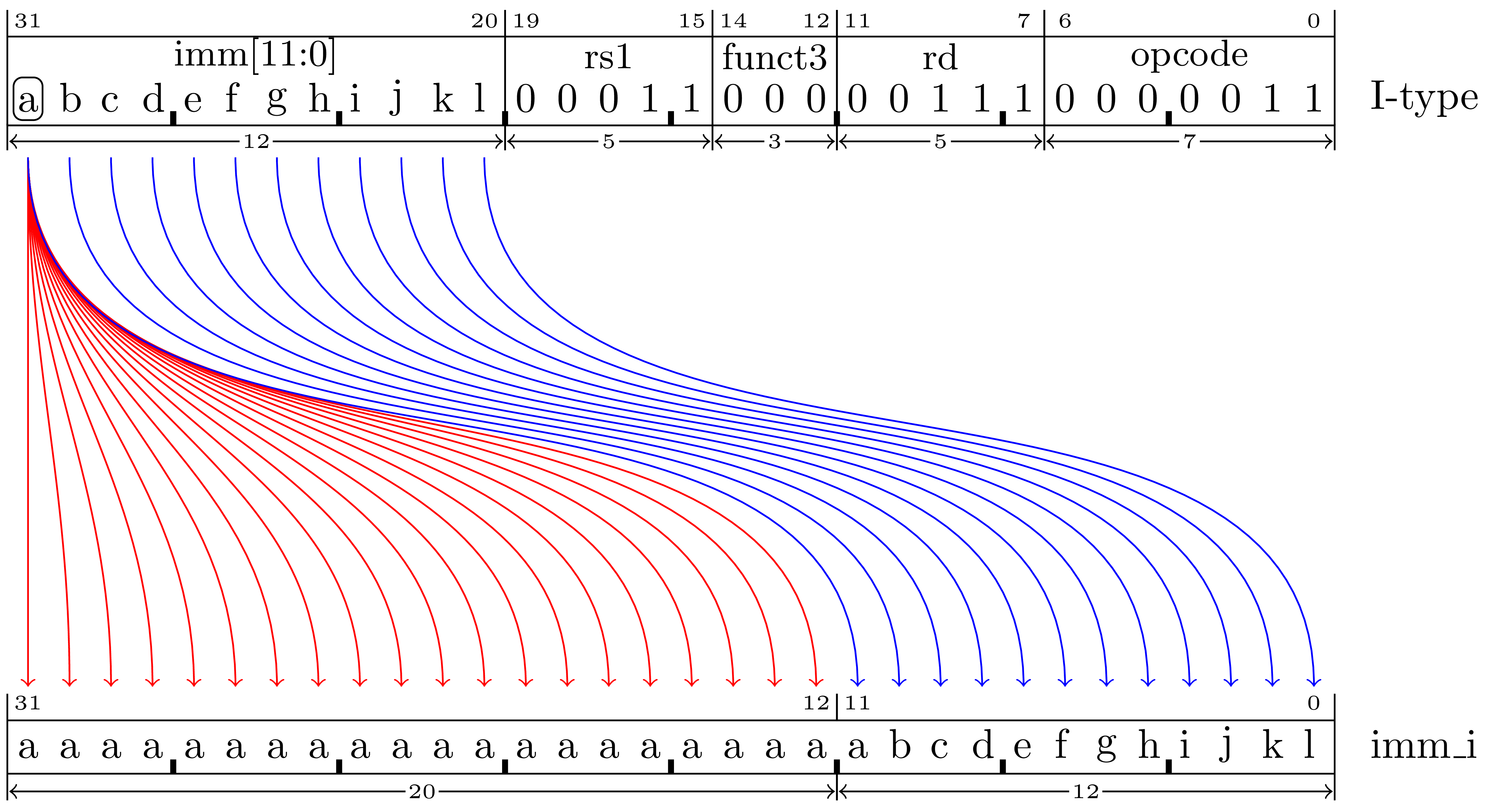
The I-type instruction format is used to encode instructions with a signed 12-bit immediate operand with a range of \([-2048..2047]\), an rd register, and an rs1 register.
If XLEN=32 then the 12-bit imm value example will extracted from the instruction and converted as shown in Figure 5.8 to form the imm_i value.
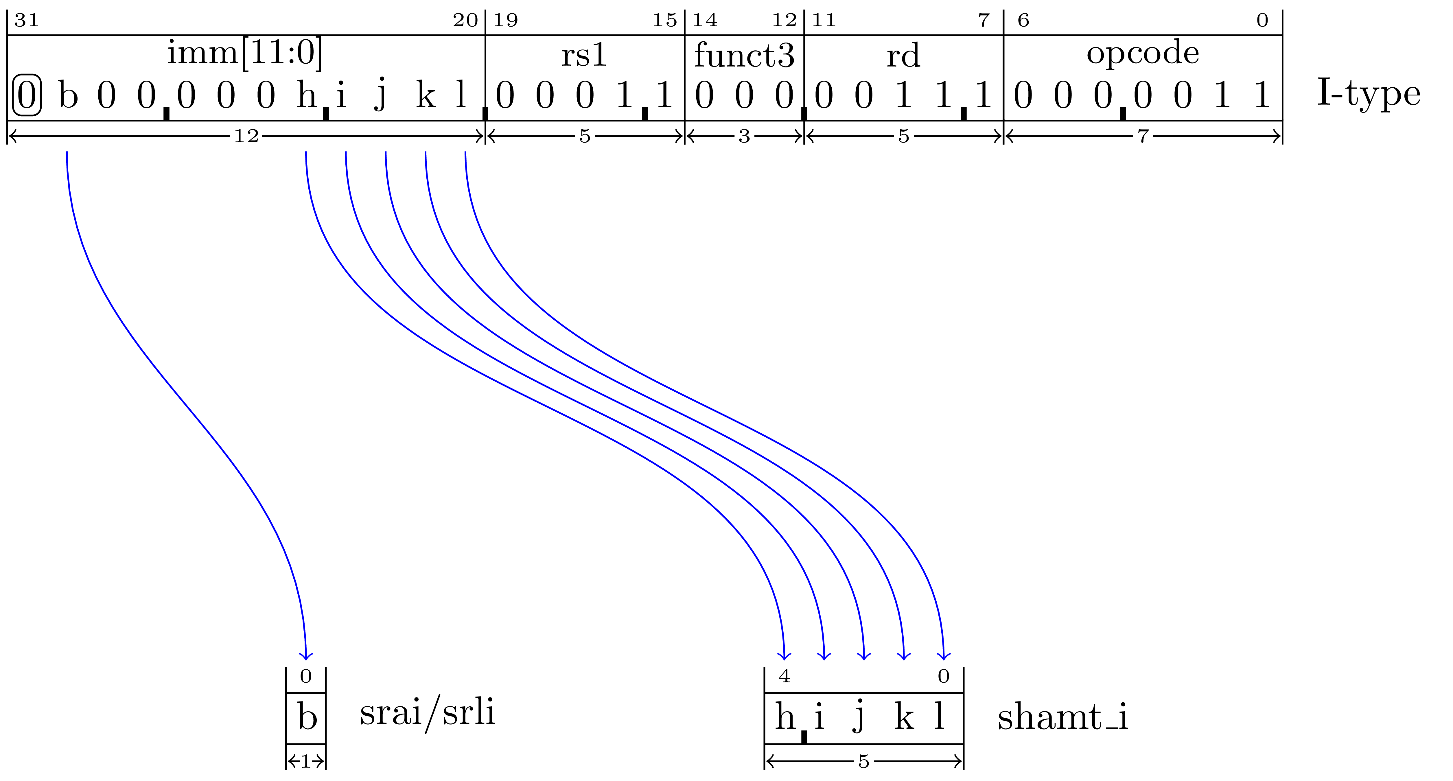
A special case of the I-type is used for shift-immediate instructions where the imm field is used to represent the number of bit positions to shift as shown in Figure 5.9. In this variation, the least significant five bits of the imm field are extracted to form the shamt_i value.2
Note also that bit 30 (the imm instruction field bit labeled ‘b’) is used to select between arithmetic and logical shifting.
 00002640: 6f 00 00 00 6f 00 00 00  b7 87 00 00 03 a5 07 43 *o...o..........C*
 00002650: 67 80 00 00 00 00 00 00  76 61 6c 3d 00 00 00 00 *g.......val=....*
 00002660: 00 00 00 00 80 84 2e 41  1f 85 45 41 80 40 9a 44 *.......A..EA.@.D*
 00002670: 4f 11 f3 c3 6e 8a 67 41  20 1b 00 00 20 1b 00 00 *O...n.gA ... ...*
 00002680: 44 1b 00 00 14 1b 00 00  14 1b 00 00 04 1c 00 00 *D...............*
addi rd,rs1,imm
Set register rd to rs1 + imm_i.
andi rd,rs1,imm
Set register rd to the bitwise and of rs1 and imm_i.
For example, if x17 = 0x55551111 then the instruction andi x12,x17,0x0ff will set x12 to the value 0x00000011.
Recall that imm is sign-extended. Therefore if x17 = 0x55551111 then the instruction andi x12,x17,0x800 will set x12 to the value 0x55551000.
jalr rd,imm(rs1)
Set register rd to the address of the next instruction that would otherwise be executed (the address of the jalr instruction + 4) and then jump to an address given by the sum of the rs1 register and the imm_i value as decoded from the instruction shown in Figure 5.8.
Note that the pc register can never refer to an odd address. This instruction will explicitly set the LSB to zero regardless of the value of the value of the calculated target address.
lb rd,imm(rs1)
Set register rd to the value of the sign-extended byte fetched from the memory address given by the sum of rs1 and imm_i.
For example, given the memory contents shown in Figure 5.10, if register x13 = 0x00002650 then the instruction lb x12,1(x13) will set x12 to the value 0xffffff80.
lbu rd,imm(rs1)
Set register rd to the value of the zero-extended byte fetched from the memory address given by the sum of rs1 and imm_i.
For example, given the memory contents shown in Figure 5.10, if register x13 = 0x00002650 then the instruction lbu x12,1(x13) will set x12 to the value 0x00000080.
lh rd,imm(rs1)
Set register rd to the value of the sign-extended 16-bit little-endian half-word value fetched from the memory address given by the sum of rs1 and imm_i.
For example, given the memory contents shown in Figure 5.10, if register x13 = 0x00002650 then the instruction lh x12,-2(x13) will set x12 to the value 0x00004307.
If register x13 = 0x00002650 then the instruction lh x12,-8(x13) will set x12 to the value 0xffff87b7.
lhu rd,imm(rs1)
Set register rd to the value of the zero-extended 16-bit little-endian half-word value fetched from the memory address given by the sum of rs1 and imm_i.
For example, given the memory contents shown in Figure 5.10, if register x13 = 0x00002650 then the instruction lhu x12,-2(x13) will set x12 to the value 0x00004307.
If register x13 = 0x00002650 then the instruction lhu x12,-8(x13) will set x12 to the value 0x000087b7.
lw rd,imm(rs1)
Set register rd to the value of the sign-extended 32-bit little-endian word value fetched from the memory address given by the sum of rs1 and imm_i.
For example, given the memory contents shown in Figure 5.10, if register x13 = 0x00002650 then the instruction lw x12,-4(x13) will set x12 to the value 4307a503.
ori rd,rs1,imm
Set register rd to the bitwise or of rs1 and imm_i.
For example, if x17 = 0x55551111 then the instruction ori x12,x17,0x0ff will set x12 to the value 0x555511ff.
Recall that imm is sign-extended. Therefore if x17 = 0x55551111 then the instruction ori x12,x17,0x800 will set x12 to the value 0xfffff911.
slli rd,rs1,imm
Shift rs1 left by the number of bits specified in shamt_i (as shown in Figure 5.9) and store the result in rd.3
For example, if x17 = 0x12345678 then the instruction slli x12,x17,4 will set x12 to the value 0x23456780.
slti rd,rs1,imm
If the signed integer value in rs1 is less than the signed integer value in imm_i then set rd to 1. Otherwise, set rd to 0.
sltiu rd,rs1,imm
If the unsigned integer value in rs1 is less than the unsigned integer value in imm_i then set rd to 1. Otherwise, set rd to 0.
Note that imm_i is always created by sign-extending the imm value as shown in Figure 5.8 even though it is then later used as an unsigned integer for the purposes of comparing its magnitude to the unsigned value in rs1. Therefore, this instruction provides a method to compare rs1 to a value in the ranges of \([\text {\tt 0}..\text {\tt 0x7ff}]\) and \([\text {\tt 0xfffff800}..\text {\tt 0xffffffff}]\).
srai rd,rs1,imm
Arithmetic-shift rs1 right by the number of bits specified in shamt_i (as shown in Figure 5.9) and store the result in rd.3
For example, if x17 = 0x87654321 then the instruction srai x12,x17,4 will set x12 to the value 0xf8765432.
Note that the value of bit 30 must be 1 for this instruction. (The value of bit 30 is how the srai instruction is differentiated from the srli instruction.)
srli rd,rs1,imm
Logic-shift rs1 right by the number of bits specified in shamt_i (as shown in Figure 5.9) and store the result in rd.3
For example, if x17 = 0x87654321 then the instruction srli x12,x17,4 will set x12 to the value 0x08765432.
Note that the value of bit 30 must be 0 for this instruction. (The value of bit 30 is how the srli instruction is differentiated from the srai instruction.)
xori rd,rs1,imm
Set register rd to the bitwise xor of rs1 and imm_i.
For example, if x17 = 0x55551111 then the instruction xori x12,x17,0x0ff will set x12 to the value 0x555511ee.
Recall that imm is sign-extended. Therefore if x17 = 0x55551111 then xori x12,x17,0x800 will set x12 to the value 0xaaaae911.
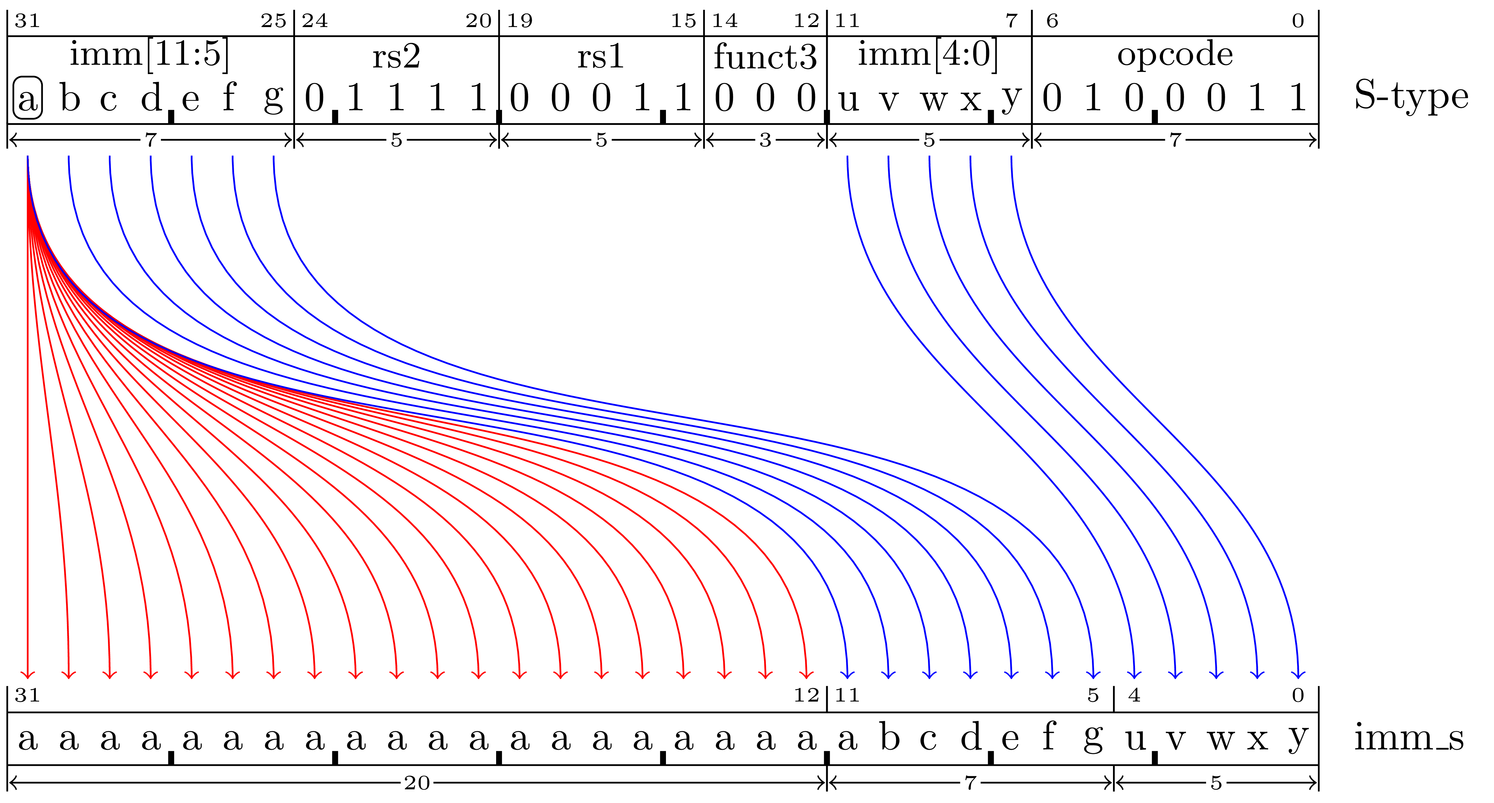
The S-type instruction format is used to encode instructions with a signed 12-bit immediate operand with a range of \([-2048..2047]\), an rs1 register, and an rs2 register.
If XLEN=32 then the 12-bit imm value example will extracted from the instruction and converted as shown Figure 5.11 to form the imm_s value.
sb rs2,imm(rs1)
Set the byte of memory at the address given by the sum of rs1 and imm_s to the 8 LSBs of rs2.
For example, given the memory contents shown in Figure 5.10, if registers x13 = 0x00002650 and x12 = 0x12345678 then the instruction sb x12,1(x13) will change the memory byte at address 0x00002651 from 0x80 to 0x78 resulting in:
      00002640: 6f 00 00 00 6f 00 00 00  b7 87 00 00 03 a5 07 43 *o...o..........C*
      00002650: 67 78 00 00 00 00 00 00  76 61 6c 3d 00 00 00 00 *gx......val=....*
      00002660: 00 00 00 00 80 84 2e 41  1f 85 45 41 80 40 9a 44 *.......A..EA.@.D*
      00002670: 4f 11 f3 c3 6e 8a 67 41  20 1b 00 00 20 1b 00 00 *O...n.gA ... ...*
      00002680: 44 1b 00 00 14 1b 00 00  14 1b 00 00 04 1c 00 00 *D...............*
sh rs2,imm(rs1)
Set the 16-bit half-word of memory at the address given by the sum of rs1 and imm_s to the 16 LSBs of rs2.
For example, given the memory contents shown in Figure 5.10, if registers x13 = 0x00002650 and x12 = 0x12345678 then the instruction sh x12,2(x13) will change the memory half-word at address 0x00002652 from 0x0000 to 0x5678 resulting in:
      00002640: 6f 00 00 00 6f 00 00 00  b7 87 00 00 03 a5 07 43 *o...o..........C*
      00002650: 67 80 78 56 00 00 00 00  76 61 6c 3d 00 00 00 00 *g.xV....val=....*
      00002660: 00 00 00 00 80 84 2e 41  1f 85 45 41 80 40 9a 44 *.......A..EA.@.D*
      00002670: 4f 11 f3 c3 6e 8a 67 41  20 1b 00 00 20 1b 00 00 *O...n.gA ... ...*
      00002680: 44 1b 00 00 14 1b 00 00  14 1b 00 00 04 1c 00 00 *D...............*
sw rs2,imm(rs1)
Store the 32-bit value in rs2 into the memory at the address given by the sum of rs1 and imm_s.
For example, given the memory contents shown in Figure 5.10, if registers x13 = 0x00002650 and x12 = 0x12345678 then the instruction sw x12,0(x13) will change the memory word at address 0x00002650 from 0x00008067 to 0x12345678 resulting in:
      00002640: 6f 00 00 00 6f 00 00 00  b7 87 00 00 03 a5 07 43 *o...o..........C*
      00002650: 78 56 34 12 00 00 00 00  76 61 6c 3d 00 00 00 00 *xV4.....val=....*
      00002660: 00 00 00 00 80 84 2e 41  1f 85 45 41 80 40 9a 44 *.......A..EA.@.D*
      00002670: 4f 11 f3 c3 6e 8a 67 41  20 1b 00 00 20 1b 00 00 *O...n.gA ... ...*
      00002680: 44 1b 00 00 14 1b 00 00  14 1b 00 00 04 1c 00 00 *D...............*
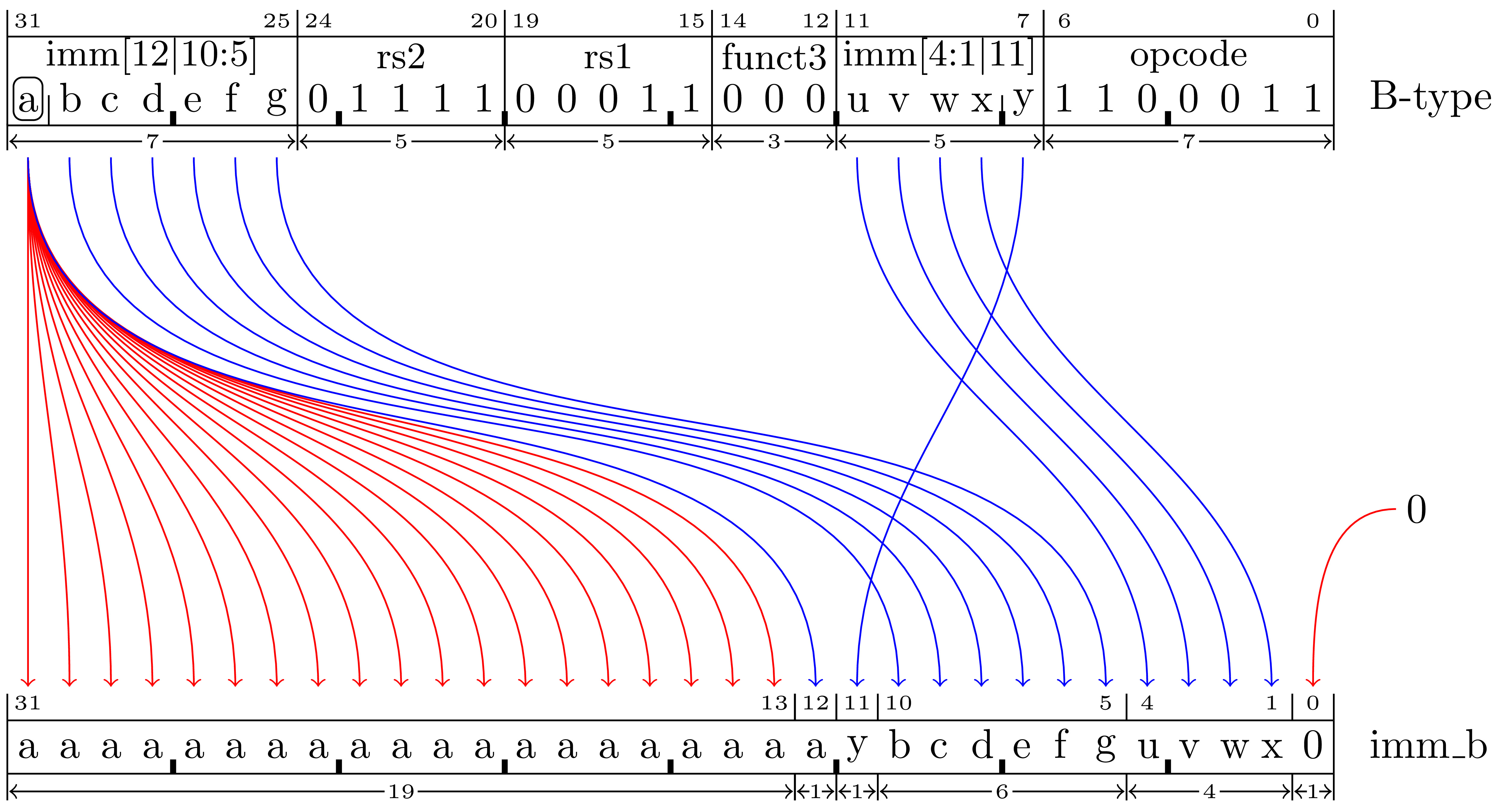
The B-type instruction format is used for branch instructions that require an even immediate value that is used to determine the branch target address as an offset from the current instruction’s address.
If XLEN=32 then the 12-bit imm value example will extracted from the instruction and converted as shown in Figure 5.12 to form the imm_b value.
Note that imm_b is expressed in the instruction as a target address that is converted to an even 13-bit value in the range of \([-4096..4094]\) \([\)-0x1000..0x0ffe\(]\) representing a pc-relative offset to the target address. For example, consider the branch instructions in the following code:
00000000: 00520063  beq    x4,x5,0x0    # branches to self (address 0x0)
00000004: 00520463  beq    x4,x5,0xc    # branches to address 0xc
00000008: fe520ce3  beq    x4,x5,0x0    # branches to address 0x0
0000000c: 00100073  ebreak
The instruction at address 0x0 has a target address of zero and imm_b is zero because the offset from the “current instruction” to the target is zero.4
The instruction at address 0x4 has a target address of 0xc and it has an imm_b of 0x08 because 0x4 + 0x08 = 0x0c.
The instruction at address 0x8 has a target address of zero and imm_b is 0xfffffff8 (-8) because 0x8 + 0xfffffff8 = 0x0.
beq rs1,rs2,pcrel_13
If rs1 is equal to rs2 then add imm_b to the pc register.
bge rs1,rs2,pcrel_13
If the signed value in rs1 is greater than or equal to the signed value in rs2 then add imm_b to the pc register.
bgeu rs1,rs2,pcrel_13
If the unsigned value in rs1 is greater than or equal to the unsigned value in rs2 then add imm_b to the pc register.
blt rs1,rs2,pcrel_13
If the signed value in rs1 is less than the signed value in rs2 then add imm_b to the pc register.
bltu rs1,rs2,pcrel_13
If the unsigned value in rs1 is less than the unsigned value in rs2 then add imm_b to the pc register.
bne rs1,rs2,pcrel_13
If rs1 is not equal to rs2 then add imm_b to the pc register.
The registers are names x0 through x31 and have aliases suited to their conventional use. The following table describes each register.
Note that the calling calling convention specifies that only some of the registers are to be saved by functions if they alter their contents. The idea being that accessing memory is time-consuming and that by classifying some registers as “temporary” (not saved by any function that alter its contents) it is possible to carefully implement a function with less need to store register values on the stack in order to use them to perform the operations of the function.
The lack of grouping the temporary and saved registers is due to the fact that the E extension only has the first 16 registers and some of the instructions in the C extension can only refer to the first 16 registers.
| Reg | ABI/Alias | Description | Saved |
| x0 | zero | Hard-wired zero | |
| x1 | ra | Return address | |
| x2 | sp | Stack pointer | yes |
| x3 | gp | Global pointer | |
| x4 | tp | Thread pointer | |
| x5 | t0 | Temporary/alternate link register | |
| x6-7 | t1-2 | Temporaries | |
| x8 | s0/fp | Saved register/frame pointer | yes |
| x9 | s1 | Saved register | yes |
| x10-11 | a0-1 | Function arguments/return value | |
| x12-17 | a2-7 | Function arguments | |
| x18-27 | s2-11 | Saved registers | yes |
| x28-31 | t3-6 | Temporaries | |
Note that RISC-V is a little-endian machine.
All instructions must be naturally aligned to their 4-byte boundaries. [?, p. 5]
If a RISC-V processor implements the C (compressed) extension then instructions may be aligned to 2-byte boundaries.[?, p. 68]
Data alignment is not necessary but unaligned data can be inefficient. Accessing unaligned data using any of the load or store instructions can also prevent a memory access from operating atomically. [?, p.19]
1 When XLEN is 64 or 128, the shift distance will be given by the least-significant 6 or 7 bits of rs2 respectively. For more information on how shifting works, see section 2.4.
2When XLEN is 64 or 128, the shamt_i field will consist of 6 or 7 bits respectively.
3 When XLEN is 64 or 128, the shift distance will be given by the least-significant 6 or 7 bits of the imm field respectively. For more information on how shifting works, see section 2.4.
4This is in contrast to many other instruction sets with pc-relative addressing modes that express a branch target offset from the “next instruction.”