This chapter introduces each of the RV32I instructions by developing programs that demonstrate their usefulness.
It is a good idea to learn how to stop before learning how to go!
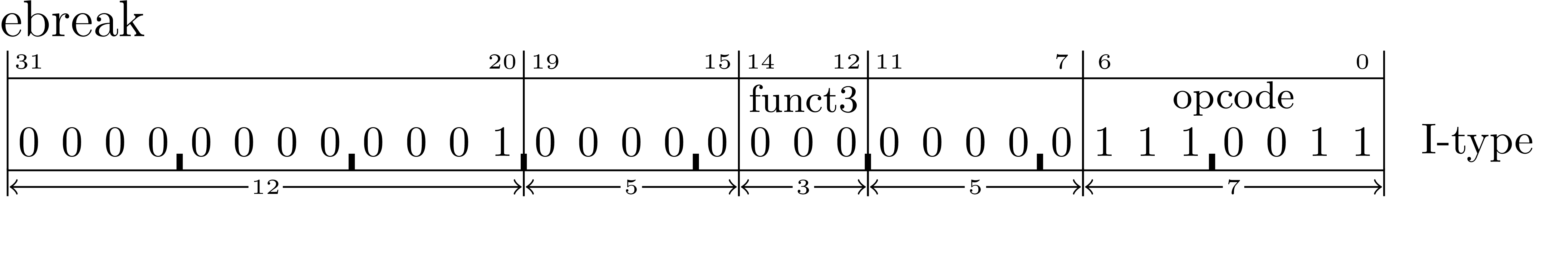
The ebreak instruction exists for the sole purpose of transferring control back to a debugging environment.[?, p. 24]
When rvddt executes an ebreak instruction, it will immediately terminate any executing trace or go
command currently executing and return to the command prompt without advancing the pc
register.
The machine language encoding shows that ebreak has no operands.
examples/chapter04/ebreak/ebreak.out demonstrates that since rvddt does not advance the pc
when it encounters an ebreak instruction, subsequent trace and/or go commands will
re-execute the same ebreak and halt the simulation again (and again). This feature is
intended to help prevent overzealous users from accidently running past the end of a code
fragment.1
     .text              # put this into the text section
2    .align  2          # align to a multiple of 4
3    .globl  _start
4
5_start:
6    ebreak
 $ rvddt -f ebreak.bin
2sp initialized to top of memory: 0x0000fff0
3Loading ’ebreak.bin’ to 0x0
4This is rvddt.  Enter ? for help.
5ddt> d 0 16
6 00000000: 73 00 10 00 a5 a5 a5 a5  a5 a5 a5 a5 a5 a5 a5 a5 *s...............*
7ddt> r
8   x0 00000000 f0f0f0f0 0000fff0 f0f0f0f0  f0f0f0f0 f0f0f0f0 f0f0f0f0 f0f0f0f0
9   x8 f0f0f0f0 f0f0f0f0 f0f0f0f0 f0f0f0f0  f0f0f0f0 f0f0f0f0 f0f0f0f0 f0f0f0f0
10  x16 f0f0f0f0 f0f0f0f0 f0f0f0f0 f0f0f0f0  f0f0f0f0 f0f0f0f0 f0f0f0f0 f0f0f0f0
11  x24 f0f0f0f0 f0f0f0f0 f0f0f0f0 f0f0f0f0  f0f0f0f0 f0f0f0f0 f0f0f0f0 f0f0f0f0
12   pc 00000000
13ddt> ti 0 1000
1400000000: ebreak
15ddt> ti
1600000000: ebreak
17ddt> g 0
1800000000: ebreak
19ddt> r
20   x0 00000000 f0f0f0f0 0000fff0 f0f0f0f0  f0f0f0f0 f0f0f0f0 f0f0f0f0 f0f0f0f0
21   x8 f0f0f0f0 f0f0f0f0 f0f0f0f0 f0f0f0f0  f0f0f0f0 f0f0f0f0 f0f0f0f0 f0f0f0f0
22  x16 f0f0f0f0 f0f0f0f0 f0f0f0f0 f0f0f0f0  f0f0f0f0 f0f0f0f0 f0f0f0f0 f0f0f0f0
23  x24 f0f0f0f0 f0f0f0f0 f0f0f0f0 f0f0f0f0  f0f0f0f0 f0f0f0f0 f0f0f0f0 f0f0f0f0
24   pc 00000000
25ddt> x
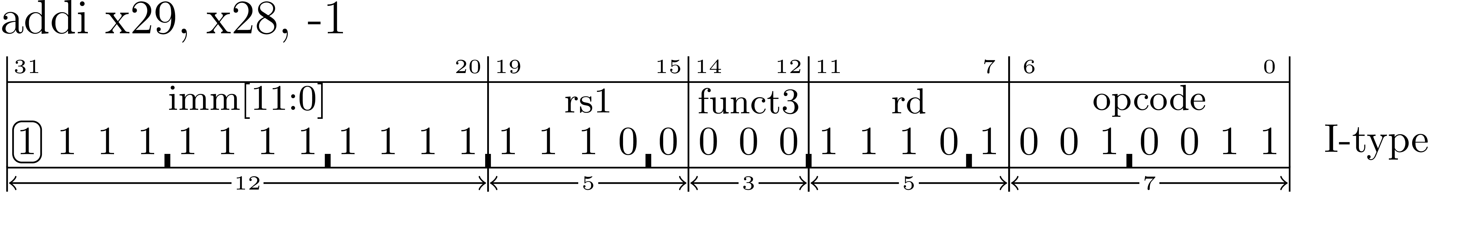
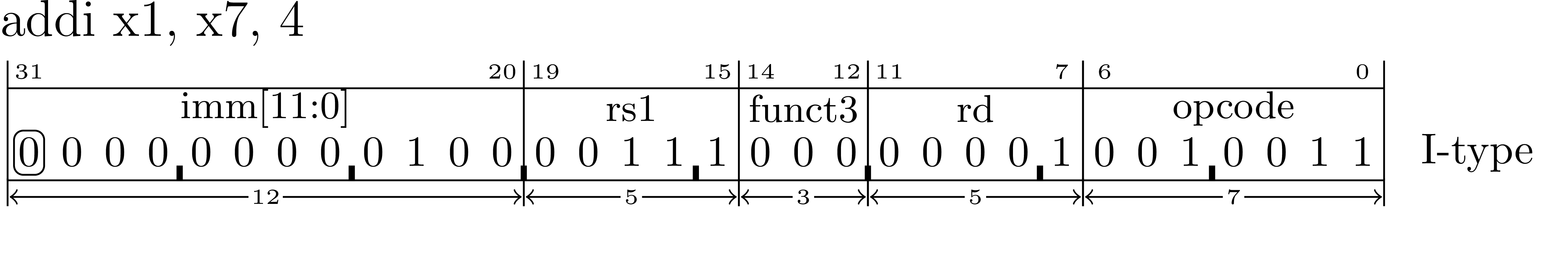
The detailed description of how the addi instruction is executed is that it:
Sign-extends the immediate operand.
Add the sign-extended immediate operand to the contents of the rs1 register.
Store the sum in the rd register.
Add four to the pc register (point to the next instruction.)
In the following example rs1 = x28, rd = x29 and the immediate operand is -1.
Depending on the values of the fields in this instruction a number of different operations can be performed. The most obvious is that it can add things. But it can also be used to copy registers, set a register to zero and even, when you need to, accomplish nothing.
It might seem odd but it is sometimes important to be able to execute an instruction
that accomplishes nothing while simply advancing the pc to the next instruction.
One reason for this is to fill unused memory between two instructions in a
program.2
An instruction that accomplishes nothing is called a nop (sometimes systems call these noop). The
name means no operation. The intent of a nop is to execute without having any side effects other
than to advance the pc register.
The addi instruction can serve as a nop by coding it like this:
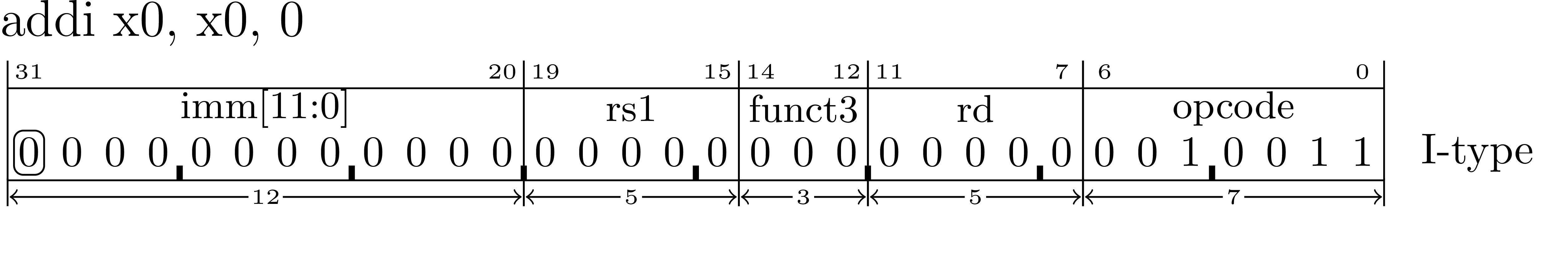
The result will be to add zero to zero and discard the result (because you can never store a value into the x0 register.)
The RISC-V assembler provides a pseudoinstruction specifically for this purpose that you can use to improve the readability of your code. Note that the addi and nop instructions in examples/chapter04/nop/nop.S are assembled into the exact same binary machine instructions as can be seen by comparing it to objdump examples/chapter04/nop/nop.lst, and rvddt examples/chapter04/nop/nop.out output.
     .text              # put this into the text section
2    .align  2          # align to a multiple of 4
3    .globl  _start
4
5_start:
6    addi    x0, x0, 0  # these two instructions assemble into the same thing!
7    nop
8
9    ebreak
 nop:     file format elf32-littleriscv
2Disassembly of section .text:
300000000 <_start>:
4   0:  00000013           nop
5   4:  00000013           nop
6   8:  00100073           ebreak
 $ rvddt -f nop.bin
2sp initialized to top of memory: 0x0000fff0
3Loading ’nop.bin’ to 0x0
4This is rvddt.  Enter ? for help.
5ddt> d 0 16
6 00000000: 13 00 00 00 13 00 00 00  73 00 10 00 a5 a5 a5 a5 *........s.......*
7ddt> r
8   x0 00000000 f0f0f0f0 0000fff0 f0f0f0f0  f0f0f0f0 f0f0f0f0 f0f0f0f0 f0f0f0f0
9   x8 f0f0f0f0 f0f0f0f0 f0f0f0f0 f0f0f0f0  f0f0f0f0 f0f0f0f0 f0f0f0f0 f0f0f0f0
10  x16 f0f0f0f0 f0f0f0f0 f0f0f0f0 f0f0f0f0  f0f0f0f0 f0f0f0f0 f0f0f0f0 f0f0f0f0
11  x24 f0f0f0f0 f0f0f0f0 f0f0f0f0 f0f0f0f0  f0f0f0f0 f0f0f0f0 f0f0f0f0 f0f0f0f0
12   pc 00000000
13ddt> ti 0 1000
1400000000: 00000013  addi    x0, x0, 0     # x0 = 0x00000000 = 0x00000000 + 0x00000000
1500000004: 00000013  addi    x0, x0, 0     # x0 = 0x00000000 = 0x00000000 + 0x00000000
1600000008: ebreak
17ddt> r
18   x0 00000000 f0f0f0f0 0000fff0 f0f0f0f0  f0f0f0f0 f0f0f0f0 f0f0f0f0 f0f0f0f0
19   x8 f0f0f0f0 f0f0f0f0 f0f0f0f0 f0f0f0f0  f0f0f0f0 f0f0f0f0 f0f0f0f0 f0f0f0f0
20  x16 f0f0f0f0 f0f0f0f0 f0f0f0f0 f0f0f0f0  f0f0f0f0 f0f0f0f0 f0f0f0f0 f0f0f0f0
21  x24 f0f0f0f0 f0f0f0f0 f0f0f0f0 f0f0f0f0  f0f0f0f0 f0f0f0f0 f0f0f0f0 f0f0f0f0
22   pc 00000008
23ddt> x
By adding zero to one register and storing the sum in another register the addi instruction can be
used to copy the value stored in one register to another register. The following instruction will copy
the contents of t4 into t3.
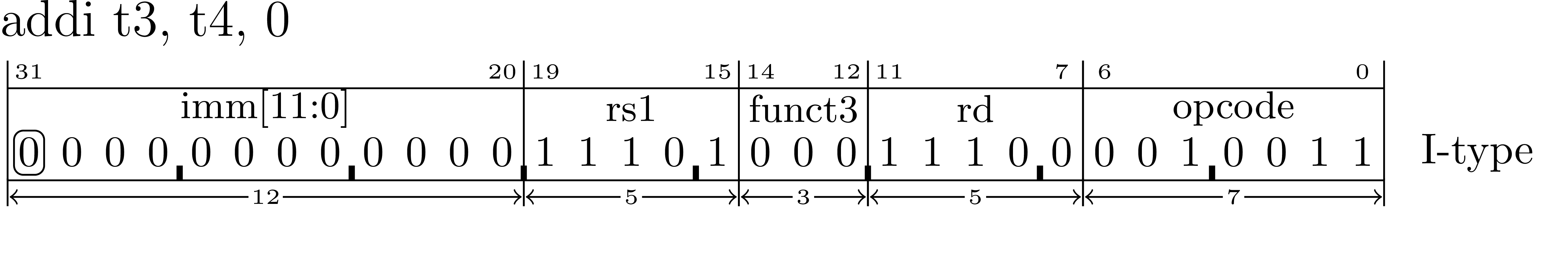
This is a commonly required operation. To make your intent clear you may use the mv pseudoinstruction for this purpose.
examples/chapter04/mv/mv.S shows the source of a program that is dumped in examples/chapter04/mv/mv.lst illustrating that the assembler has generated the same machine instruction (0x000e8e13 at addresses 0x0 and 0x4) for both of the instructions.
     .text              # put this into the text section
2    .align  2          # align to a multiple of 4
3    .globl  _start
4
5_start:
6    addi    t3, t4, 0  # t3 = t4
7    mv      t3, t4      # t3 = t4
8
9    ebreak
 mv:     file format elf32-littleriscv
2Disassembly of section .text:
300000000 <_start>:
4   0:  000e8e13           mv  t3,t4
5   4:  000e8e13           mv  t3,t4
6   8:  00100073           ebreak
Recall that x0 always contains the value zero. Any register can be set to zero by copying the contents of x0 using
mv (aka addi).3
For example, to set t3 to zero:

     .text              # put this into the text section
2    .align  2          # align to a multiple of 4
3    .globl  _start
4
5_start:
6    mv      t3, x0      # t3 = 0
7
8    ebreak
examples/chapter04/mvzero/mv.out traces the execution of the program in examples/chapter04/mvzero/mv.S
showing how t3 is changed from 0xf0f0f0f0 (seen on \(\ell 16\)) to 0x00000000 (seen on \(\ell 26\).)
 $ rvddt -f mv.bin
2sp initialized to top of memory: 0x0000fff0
3Loading ’mv.bin’ to 0x0
4This is rvddt.  Enter ? for help.
5ddt> a
6ddt> d 0 16
7 00000000: 13 0e 00 00 73 00 10 00  a5 a5 a5 a5 a5 a5 a5 a5 *....s...........*
8ddt> t 0 1000
9 zero  x0 00000000  ra  x1 f0f0f0f0  sp  x2 0000fff0  gp  x3 f0f0f0f0
10   tp  x4 f0f0f0f0  t0  x5 f0f0f0f0  t1  x6 f0f0f0f0  t2  x7 f0f0f0f0
11   s0  x8 f0f0f0f0  s1  x9 f0f0f0f0  a0 x10 f0f0f0f0  a1 x11 f0f0f0f0
12   a2 x12 f0f0f0f0  a3 x13 f0f0f0f0  a4 x14 f0f0f0f0  a5 x15 f0f0f0f0
13   a6 x16 f0f0f0f0  a7 x17 f0f0f0f0  s2 x18 f0f0f0f0  s3 x19 f0f0f0f0
14   s4 x20 f0f0f0f0  s5 x21 f0f0f0f0  s6 x22 f0f0f0f0  s7 x23 f0f0f0f0
15   s8 x24 f0f0f0f0  s9 x25 f0f0f0f0 s10 x26 f0f0f0f0 s11 x27 f0f0f0f0
16   t3 x28 f0f0f0f0  t4 x29 f0f0f0f0  t5 x30 f0f0f0f0  t6 x31 f0f0f0f0
17       pc 00000000
1800000000: 00000e13  addi    t3, zero, 0   # t3 = 0x00000000 = 0x00000000 + 0x00000000
19 zero  x0 00000000  ra  x1 f0f0f0f0  sp  x2 0000fff0  gp  x3 f0f0f0f0
20   tp  x4 f0f0f0f0  t0  x5 f0f0f0f0  t1  x6 f0f0f0f0  t2  x7 f0f0f0f0
21   s0  x8 f0f0f0f0  s1  x9 f0f0f0f0  a0 x10 f0f0f0f0  a1 x11 f0f0f0f0
22   a2 x12 f0f0f0f0  a3 x13 f0f0f0f0  a4 x14 f0f0f0f0  a5 x15 f0f0f0f0
23   a6 x16 f0f0f0f0  a7 x17 f0f0f0f0  s2 x18 f0f0f0f0  s3 x19 f0f0f0f0
24   s4 x20 f0f0f0f0  s5 x21 f0f0f0f0  s6 x22 f0f0f0f0  s7 x23 f0f0f0f0
25   s8 x24 f0f0f0f0  s9 x25 f0f0f0f0 s10 x26 f0f0f0f0 s11 x27 f0f0f0f0
26   t3 x28 00000000  t4 x29 f0f0f0f0  t5 x30 f0f0f0f0  t6 x31 f0f0f0f0
27       pc 00000004
2800000004: ebreak
29ddt> x
    addi    t0, zero, 4     # t0 = 4
    addi    t0, t0, 100     # t0 = 104

    addi    t0, zero, 0x123     # t0 = 0x123
    addi    t0, t0, 0xfff       # t0 = 0x122 (subtract 1)

    addi    t0, zero, 0xfff     # t0 = 0xffffffff (-1)  (diagram out the chaining carry)
                                # refer back to the overflow/truncation discussion in binary chapter

addi x0, x0, 0 # no operation (pseudo: nop)
addi rd, rs, 0 # copy reg rs to rd (pseudo: mv rd, rs)
Ideas for the order of introducing instructions.
    andi
    ori
    xori

    slti
    sltiu
    srai
    slli
    srli
RV is a load-store architecture. This means that the only way that the CPU can interact with the memory is via the load and store instructions. All other data manipulation must be performed on register values.
Copying values from memory to a register (first examples using regs set with addi):
    lb
    lh
    lw
    lbu
    lhu
Copying values from a register to memory:
    sb
    sh
    sw
    add
    sub
    and
    or
    sra
    srl
    sll
    xor
    sltu
    slt
    addi        // useful for values from -2048 to 2047
    lui         // useful for loading any multiple of 0x1000

    Setting a register to any other value must be done using a combo of insns:

    auipc       // Load an address relative the the current PC (see la pseudo)
    addi

    lui         // Load constant into into bits 31:12  (see li pseudo)
    addi        // add a constant to fill in bits 11:0
                    if bit 11 is set then need to +1 the lui value to compensate
Start to introduce addressing here?
    beq
    bne
    blt
    bge
    bltu
    bgeu

    bgt rs, rt, offset      # pseudo for: blt rt, rs, offset    (reverse the operands)
    ble rs, rt, offset      # pseudo for: bge rt, rs, offset    (reverse the operands)
    bgtu rs, rt, offset     # pseudo for: bltu rt, rs, offset   (reverse the operands)
    bleu rs, rt, offset     # pseudo for: bgeu rt, rs, offset   (reverse the operands)

    beqz rs, offset         # pseudo for: beq rs, x0, offset
    bnez rs, offset         # pseudo for: bne rs, x0, offset
    blez rs, offset         # pseudo for: bge x0, rs, offset
    bgez rs, offset         # pseudo for: bge rs, x0, offset
    bltz rs, offset         # pseudo for: blt rs, x0, offset
    bgtz rs, offset         # pseudo for: blt x0, rs, offset
Introduce and present subroutines but not nesting until introduce stack operations.
    jal
    jalr
    li   rd,constant
                     lui      rd,(constant + 0x00000800) >> 12
                     addi     rd,rd,(constant & 0x00000fff)

    la   rd,label
                     auipc    rd,((label-.) + 0x00000800) >> 12
                     addi     rd,rd,((label-(.-4)) & 0x00000fff)

    l{b|h|w} rd,label
                     auipc    rd,((label-.) + 0x00000800) >> 12
                     l{b|h|w} rd,((label-(.-4)) & 0x00000fff)(rd)

    s{b|h|w} rd,label,rt          # rt used as a temp reg for the operation (default=x6)
                     auipc    rt,((label-.) + 0x00000800) >> 12
                     s{b|h|w} rd,((label-(.-4)) & 0x00000fff)(rt)

    call label       auipc    x1,((label-.) + 0x00000800) >> 12
                     jalr     x1,((label-(.-4)) & 0x00000fff)(x1)

    tail label,rt                 # rt used as a temp reg for the operation (default=x6)
                     auipc    rt,((label-.) + 0x00000800) >> 12
                     jalr     x0,((label-(.-4)) & 0x00000fff)(rt)

    mv   rd,rs       addi     rd,rs,0

    j    label       jal      x0,label
    jal  label       jal      x1,label
    jr   rs          jalr     x0,0(rs)
    jalr rs          jalr     x1,0(rs)
    ret              jalr     x0,0(x1)
Note that the li pseudoinstruction includes an (effectively) conditional addition of 1 to the immediate operand in the lui instruction. This is because the immediate operand in the addi instruction is sign-extended before it is added to rd. If the immediate operand to the addi has its most-significant-bit set to 1 then it will have the effect of subtracting 1 from the operand in the lui instruction.
Consider the case of putting the value 0x12345800 into register x5:
li x5,0x12345800A naive (incorrect) solution might be:
    lui  x5,0x12345    // x5 = 0x12345000
    addi x5,x5,0x800   // x5 = 0x12345000 + sx(0x800) = 0x12345000 + 0xfffff800 = 0x12344800
The result of the above code is that an incorrect value has been placed into x5.
To remedy this problem, the value used in the lui instruction can be altered (by adding 1 to its operand) to compensate for the sign-extention in the addi instruction:
    lui  x5,0x12346    // x5 = 0x12346000  (note: this is 0x12345800 + 0x0800)
    addi x5,x5,0x800   // x5 = 0x12346000 + sx(0x800) = 0x12346000 + 0xfffff800 = 0x12345800
Keep in mind that the li pseudoinstruction must only increment the operand of the lui instruction when it is known that the operand of the subsequent addi instruction will be a negative number.
By adding 0x00000800 to the immediate operand of the lui instruction in this example, a carry-bit into bit-12 will be set to 1 iff the value in bits 11-0 will be treated as a negative value in the subsequent addi instruction. In other words, when bit-11 is set to 1 in the immediate operand of the li pseudoinstruction, the immediate operand of the lui instruction will be incremented by 1.
Consider the case where we wish to put the value 0x12345700 into register x5:
    lui  x5,0x12345    // x5 = 0x12345000  (note that 0x12345700 + 0x0800 = 0x12345f00)
    addi x5,x5,0x700   // x5 = 0x12345000 + sx(0x700) = 0x12345000 + 0x00000700 = 0x12345700
The sign-extension in this example performed by the addi instruction will convert the 0x700 to 0x00000700 before the addition.
Observe that 0x12345700+0x0800 = 0x12345f00 and therefore, after shifting to the right, the least significant 0xf00 is truncated, leaving 0x12345 as the immediate operand of the lui instruction. The addition of 0x0800 in this example has no effect on the immediate operand of the lui instruction because bit-11 in the original value 0x12345700 is zero.
A general algorithm for implementing the li rd,constant pseudoinstruction is:
    lui  rd,(constant + 0x00000800) >> 12
    addi rd,rd,(constant & 0x00000fff) // the 12-bit immediate is sign extended
Note that on RV64 and RV128 systems, the lui places the immediate operand into bits 31-12 and then sign-extends the result to XLEN bits.
The la (and others that use auipc such as the l{b|h|w}, s{b|h|w}, call, and tail) pseudoinstructions also compensate for a sign-ended negative number when adding a 12-bit immediate operand. The only difference is that these use a pc-relative addressing mode.
For example, consider the task of putting an address represented by the label var1 into register x10:
00010040     la     x10,var1
00010048 ...                 # note that the la pseudoinstruction expands into 8 bytes
...

         var1:
00010900     .word  999       # a 32-bit integer constant stored in memory at address var1
The la instruction in this example will expand into:
00010040     auipc x10,((var1-.) + 0x00000800) >> 12
00010044     addi  x10,x10,((var1-(.-4)) & 0x00000fff)
Note that auipc will shift the immediate operand to the left 12 bits and then add that to the pc register (see 5.3.1.)
The assembler will calculate the value of (var1-.) by subtracting the address represented by the label var1 from the address of the current instruction (which is expressed as ’.’) resulting in the number of bytes from the current instruction to the target label… which is 0x000008c0.
Therefore the expanded pseudoinstruction example will become:
00010040     auipc x10,((0x00010900 - 0x00010040) + 0x00000800) >> 12
00010044     addi  x10,x10,((0x00010900 - (0x00010044 - 4)) & 0x00000fff)   # note the extra -4 here!
After performing the subtractions, it will reduce to this:
00010040     auipc x10,(0x000008c0 + 0x00000800) >> 12
00010044     addi  x10,x10,(0x000008c0 & 0x00000fff)
Continuing to reduce the math operations we get:
00010040     auipc x10,0x00001              # 0x000008c0 + 0x00000800 = 0x000010c0
00010044     addi  x10,x10,0x8c0
Note that the la pseudoinstruction exhibits the same sort of technique as the li in that if/when the immediate operand of the addi instruction has its most significant bit set then the operand in the auipc has to be incremented by 1 to compensate.
Because expressions that refer to constants and address labels are common in assembly language programs, a shorthand notation is available for calculating the pairs of values that are used in the implementation of things like the li and la pseudoinstructions (that have to be written to compensate for the sign-extension that will take place in the immediate operand that appears in instructions like addi and jalr.)
To refer to an absolute value, the following operators can be used:
    %hi(constant)    // becomes: (constant + 0x00000800) >> 12
    %lo(constant)    // becomes: (constant & 0x00000fff)
Thus, the li pseudoinstruction can, therefore, be expressed like this:
    li   rd,constant  lui      rd,%hi(constant)
                      addi     rd,rd,%lo(constant)
The following can be used for PC-relative addresses:
    %pcrel_hi(symbol) // becomes: ((symbol-.) + 0x0800) >> 12
    %pcrel_lo(lab)    // becomes: ((symbol-lab) & 0x00000fff)
Note the subtlety involved with the lab on %pcrel_lo. It is needed to determine the address of the instruction that contains the corresponding %pcrel_hi. (The label lab MUST be on a line that used a %pcrel_hi() or get an error from the assembler.)
Thus, the la rd,label pseudoinstruction can be expressed like this:
xxx:  auipc rd,%pcrel_hi(label)
      addi  rd,rd,%pcrel_lo(xxx)  // the xxx tells pcrel_lo where to find the matching pcrel_hi
Examples of using the auipc & addi together with %pcrel_hi() and %pcrel_lo():
xxx:    auipc   t1,%pcrel_hi(yyy)     // ((yyy-.) + 0x0800) >> 12
        addi    t1,t1,%pcrel_lo(xxx)  // ((yyy-xxx) & 0x00000fff)
...
yyy:                                  // the address: yyy is saved into t1 above
...
Referencing the same %pcrel_hi in multiple subsequent uses of %pcrel_lo is legal:
label:  auipc   t1,%pcrel_hi(symbol)
        addi    t2,t1,%pcrel_lo(label)   // t2 = symbol
        addi    t3,t1,%pcrel_lo(label)   // t3 = symbol
        lw      t4,%pcrel_lo(label)(t1)  // t4 = fetch value from memory at ’symbol’
        addi    t4,t4,123                // t4 = t4 + 123
        sw      t4,%pcrel_lo(label)(t1)  // store t4 back into memory at ’symbol’
In the simplest of terms, Relaxation refers to the ability of the linker (not the compiler!) to determine if/when the instructions that were generated with the xxx_hi and xxx_lo operators are unneeded (and thus waste execution time and memory) and can therefore be removed.
However, doing so is not trivial as it will result in moving things around in memory, possibly changing the values of address labels in the already-assembled program! Therefore, while the motivation for rexation is obvious, the process of implementing it is non-trivial.
See: https://github.com/riscv/riscv-elf-psabi-doc/blob/master/riscv-elf.md
1This was one of the first enhancements I needed for myself :-)
2This can happen during the evolution of one portion of code that reduces in size but has to continue to fit into a system without altering any other code… or sometimes you just need to waste a small amount of time in a device driver.
3There are other pseudoinstructions (such as li) that can also turn into an addi instruction. Objdump might display ‘addi t3,x0,0’ as ‘mv t3,x0’ or ‘li t3,0’.